|
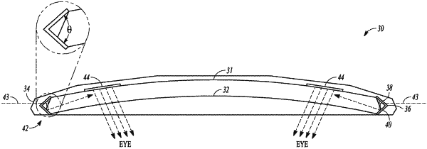
1. A waveguide for a display system comprising: a waveguide body configured to guide light through the waveguide body, the waveguide body comprising a pair of opposite major outer faces, and a peripheral edge face connecting the major outer faces; a light in-coupling region formed on the peripheral edge face of the waveguide body, the light in-coupling region including a first surface having a first set of diffraction gratings and a second surface having a second set of diffraction gratings, the first and second surfaces being angled relative to each other and wherein the light in-coupling region, including the first and second sets of diffraction gratings, extends along an entirety of the peripheral edge face of the waveguide body; and a light exit region formed along a top surface of the waveguide body, the light exit region including a third set of diffraction gratings, wherein the first set of diffraction gratings are configured to diffract light towards the second set of diffraction gratings, the second set of diffraction gratings are configured to diffract light towards the third set of diffraction gratings, and the third set of diffraction gratings are configured to diffract light towards an eye of a user.
|
