| CPC H02M 3/158 (2013.01) [H01L 25/115 (2013.01); H02M 3/155 (2013.01); H03H 7/0115 (2013.01)] | 20 Claims |

|
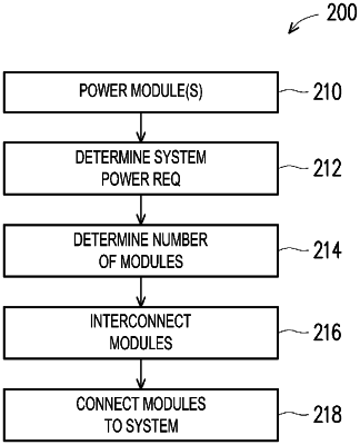
1. A method for providing power to a system, the method comprising:
providing a plurality of power modules, each of the plurality of power modules configured to output a predetermined current level, wherein each of the plurality of power modules comprises:
an input voltage terminal configured to receive a raw input voltage and a ground terminal;
a voltage regulator connected to the ground terminal and the input voltage terminal, wherein the voltage regulator comprises a first switch and a second switch;
an inductor having an inductor output connected to an interconnection terminal;
wherein each of the first switch and the second switch of the voltage regulator are stacked directly over a top side of the inductor such that the inductor is positioned directly between the voltage regulator and a substrate, wherein the inductor is stacked directly over the substrate, wherein the first switch of the voltage regulator is positioned above a first lateral side of the inductor and the second switch of the voltage regulator is positioned above a second lateral side opposite the first lateral side of the inductor, wherein the ground terminal is positioned adjacent the second lateral side, and wherein the input voltage terminal is positioned adjacent the first lateral side of the inductor;
determining power requirements for the system to be powered;
determining a number of the plurality of power modules required to meet the determined power requirements;
interconnecting the number of the plurality of power modules together; and
connecting the interconnected plurality of power modules to the system to be powered.
|