| CPC H02M 3/01 (2021.05) [H02M 1/12 (2013.01); H02M 3/33573 (2021.05); H02M 3/33576 (2013.01); H02M 3/33592 (2013.01)] | 9 Claims |
|
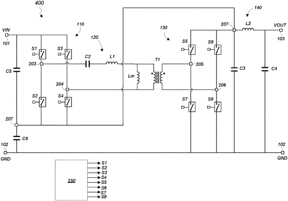
1. A resonant converter that receives a DC input voltage at an input voltage node and generates a DC output voltage at an output voltage node, the resonant converter comprising:
an inverter circuit that converts the DC input voltage to a pulsating signal;
a primary resonant tank circuit comprising a first resonant capacitor, a first resonant inductor, and a primary winding of a transformer that are connected in series, wherein the primary resonant tank circuit is connected to the inverter to receive the pulsating signal to generate a resonant tank current that flows through the primary winding of the transformer;
a rectifier that is connected to a secondary winding of the transformer to rectify a current induced in the secondary winding of the transformer by the resonant tank current;
an output capacitor that is connected to the output voltage node; and
a secondary resonant tank circuit that is disposed between the input voltage node and the output voltage node, the secondary resonant tank circuit comprising a second resonant capacitor and a second resonant inductor, wherein the secondary tank circuit has a resonant frequency that is higher than a resonant frequency of the primary resonant tank circuit;
wherein the secondary resonant tank circuit has a tank node that is connected to an input of the primary tank resonant circuit, and the tank node is connected between terminals of the second resonant capacitor and the second resonant inductor of the secondary resonant tank circuit;
wherein the inverter circuit comprises a first switch, a second switch, a third switch, and a fourth switch; first terminals of the first and third switches are connected to the input voltage node; a second terminal of the first switch and a first terminal of the second switch are connected to a first end node of the primary resonant tank circuit; a second terminal of the third switch and a first terminal of the fourth switch are connected to a second end node of the primary resonant tank circuit; and the tank node is connected to second terminals of the second and fourth switches; and
wherein the resonant converter further comprising a capacitor having a first end that is directly connected to the second terminals of the second and fourth switches and a second end that is directly connected to ground.
|