| CPC H02J 7/007182 (2020.01) [H02J 7/0063 (2013.01); H02J 7/0068 (2013.01); H02J 9/061 (2013.01); H02J 2207/20 (2020.01)] | 3 Claims |

|
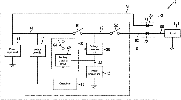
1. A charge/discharge control apparatus that controls charge/discharge in a power supply system that includes a power supply unit, a power storage unit, a first power path that is a path for supplying a load with power that is based on the power supply unit, and a second power path that is a path for supplying the load with power that is based on the power storage unit, the charge/discharge control apparatus comprising:
a first conductive path that is a path on which power that is based on the power supply unit is transmitted;
a second conductive path that is interposed between the second power path and the first conductive path;
a third conductive path that is electrically connected to the power storage unit;
a voltage conversion unit configured to perform voltage conversion between the second conductive path and the third conductive path;
a first switch that is provided between the first conductive path and the second conductive path, and is configured to switch between an on state where a current is allowed to flow from the first conductive path to the second conductive path and an off state where the current is blocked;
a second switch that is provided between the second conductive path and the second power path, and is configured to switch between an on state where a current is allowed to flow from the second conductive path to the second power path, and an off state where the current is blocked; and
an auxiliary charging unit configured to switch between a supply state where power is supplied to the power storage unit via a path different from a path including the voltage conversion unit, based on power supplied via the first conductive path, and a stopped state where the supply of power to the power storage unit is stopped;
wherein the control unit performs first control, second control, and third control,
the first control being control that turns on the first switch while causing the voltage conversion unit to perform an operation of stepping up or stepping down the voltage applied to the second conductive path and applying the thus stepped-down or stepped-up voltage to the third conductive path,
the second control being control that turns off the first switch and turns on the second switch, sets the auxiliary charging unit to the stopped state, and causes the voltage conversion unit to perform an operation of stepping up or stepping down the voltage applied to the third conductive path and applying the thus stepped-up or stepped-down voltage to the second conductive path, and
the third control being control that turns off the first switch and turns on the second switch, sets the auxiliary charging unit to the supply state, and causes the voltage conversion unit to perform a conversion operation of stepping up or stepping down the voltage applied to the third conductive path and applying the thus stepped-up or stepped-down voltage to the second conductive path.
|