| CPC G09G 3/006 (2013.01) [G01R 27/16 (2013.01); G09G 3/2007 (2013.01); G09G 3/344 (2013.01); G09G 2310/06 (2013.01); G09G 2320/0257 (2013.01)] | 6 Claims |

|
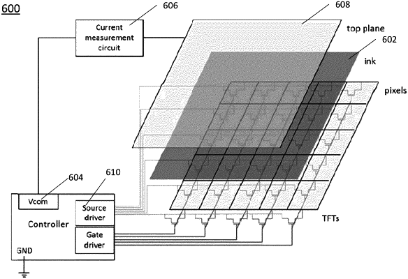
1. A method for driving an electro-optic display, the electro-optic display comprising an electrophoretic display medium disposed between a first common electrode and an array of pixel electrodes, wherein each pixel electrode is coupled to a first terminal of a storage capacitor, wherein a second terminal of each storage capacitor is coupled to second common electrode, and wherein a display controller circuit is configured to apply time-dependent voltages to the first common electrode and the second common electrode independent of one another, the method for driving comprising:
concurrently activating pixel transistors associated with a first portion of pixel electrodes;
toggling a first switch to disconnect the first common electrode from the display controller circuit and to connect the first common electrode to a first terminal of an impedance measurement circuit;
toggling a second switch to disconnect the second common electrode from the display controller circuit and to connect the second common electrode to a second terminal of the impedance measurement circuit;
injecting measurement waveforms voltages from the impedance measurement circuit into the first common electrode, the measurement waveforms comprising time-dependent voltages;
measuring a first current flowing through the impedance measurement circuit based on the measurement waveforms;
determining a first impedance of the electro-optic material in proximity to the first portion of pixel electrodes based on the first current flowing through the impedance measurement circuit and the time-dependent voltages applied to the first common electrode during the measurement waveforms;
selecting first driving waveforms to apply to each pixel electrode of the first portion of pixel electrodes based on the first impedance of the electro-optic material in proximity to the first portion of pixel electrodes;
toggling the first switch to disconnect the first common electrode from the impedance measurement circuit and to connect the first common electrode to the display controller circuit;
toggling the second switch to disconnect the second common electrode from the impedance measurement circuit and to connect the second common electrode to the display controller circuit; and
applying the first driving waveforms to the first portion of pixel electrodes, wherein the first driving waveforms comprise time-dependent voltages sufficient to change an optical state of the electro-optic display in proximity to the first portion of pixel electrodes.
|