| CPC G09B 25/06 (2013.01) | 8 Claims |

|
1. A portable simulated flood discharge culvert for surveying and mapping, comprising:
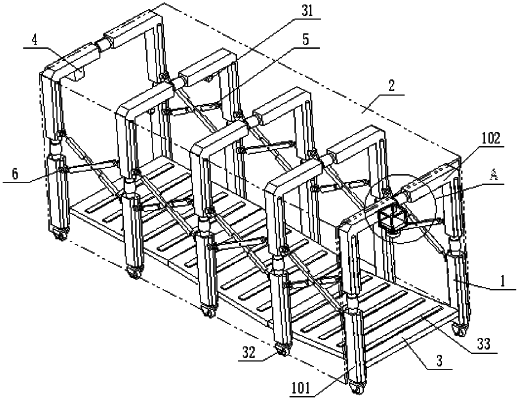
a supporting device, wherein the supporting device comprises a plurality of telescopic support rods, the telescopic support rods have U-shaped structures, and openings of the telescopic support rods are downward;
a tarpaulin, wherein the tarpaulin is covered on outer walls of the telescopic support rods, and a channel with two ends communicated is formed between the plurality of telescopic support rods and the tarpaulin;
connecting devices, wherein each of the connecting devices is installed between any two adjacent telescopic support rods;
floors, wherein a plurality of floors are provided, the plurality of floors are respectively arranged between the plurality of telescopic support rods, and top surfaces of the floors are provided with a plurality of protrusions;
adjusting devices, wherein each of the adjusting devices comprises angle adjusting mechanisms and a height adjusting mechanism, and the angle adjusting mechanisms and the height adjusting mechanism are respectively fixed on a bottom surface of each of the floors, and the angle adjusting mechanisms are fixed on two sides of the height adjusting mechanism;
a fog generating device, wherein the fog generating device is installed on any of the telescopic support rods;
a lighting part, wherein the lighting part is fixedly connected to one of the telescopic support rods located in a middle section; and
additional blocks, wherein a plurality of additional blocks are provided, and the plurality of additional blocks are all arranged on the telescopic support rods;
wherein each of the connecting devices comprises two hinged rods, middle parts of the two hinged rods are hinged by a rotating shaft, and two ends of each of the two hinged rods are respectively hinged with mounting blocks, and the mounting blocks are provided with clamping grooves; side walls of the telescopic support rods are fixedly connected with first slide bars, and each of the mounting blocks is slidably clamped on corresponding one of the first slide bars through corresponding one of the clamping grooves; chutes are formed on two opposite side walls of each of the clamping grooves, and ball cups are arranged in the chutes, and balls are rotatably arranged on the ball cups; the balls are in sliding fit with an outer wall of each of the first slide bars; a side of each of the ball cups away from each of the balls is fixedly connected with a sliding sleeve, and a second slide bar is slidably connected in the sliding sleeve; one end of the second slide bar is fixedly connected in each of the chutes, and a first spring is sleeved outside the sliding sleeve, and both ends of the first spring are fixedly connected with corresponding one of the ball cups and an inner wall of corresponding one of the chutes respectively; limiting pieces are installed on side walls of each of the clamping grooves, and the limiting pieces are in limiting fit with side walls of each of the first slide bars; and
each of the limiting pieces comprises an anti-skid block; the side walls of each of the clamping grooves are provided with mounting grooves, axes of the mounting grooves are perpendicular to an axis of each of the first slide bars; the anti-skid block is slidably arranged in each of the mounting grooves; one side of the anti-skid block is in contact fit with a side wall of each of the first slide bars, and an other side of the anti-skid block is fixedly connected with a sleeve; a side wall of each of the mounting grooves is provided with a threaded hole, and the threaded hole is threadedly connected to a bolt, and one end of the bolt is sleeved inside the sleeve and abuts against a side of the anti-skid block away from each of the first slide bars; an outer wall of the sleeve is sleeved with a second spring; one end of the second spring is fixedly connected with an inner wall of each of the mounting grooves, and an other end of the second spring is fixedly connected with the anti-skid block.
|