| CPC G02F 1/13706 (2021.01) [G02B 5/3016 (2013.01)] | 11 Claims |

|
1. An optically anisotropic film that is formed of a liquid crystal composition including a liquid crystal compound, the optically anisotropic film comprising:
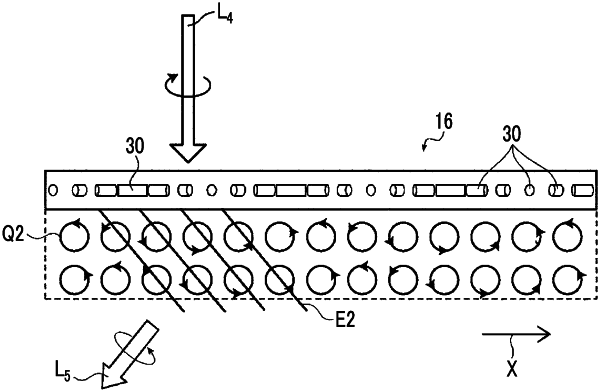
a liquid crystal alignment pattern where a direction of an optical axis derived from the liquid crystal compound changes while continuously rotating in at least one in-plane direction of the optically anisotropic film,
wherein a requirement X described below and a requirement Y1 or a requirement Y2 described below are satisfied,
the requirement X: in a case where any position on one surface of the optically anisotropic film in a cross-section of the optically anisotropic film taken along a direction in which the liquid crystal alignment pattern extends is represented by a position P1, a position at which a line and another surface of the optically anisotropic film intersect with each other is represented by a position P2, the line being formed by connecting positions at which directions of optical axes derived from the liquid crystal compounds are the same as a direction of an optical axis derived from the liquid crystal compound at the position P1 from the position P1 to the other surface of the optically anisotropic film, and a distance between the position P1 and the position P2 in the one in-plane direction of the optically anisotropic film is represented by a distance D, a first region where an angle between an optical axis derived from the liquid crystal compound at a position X on the one surface of the optically anisotropic film and an optical axis derived from the liquid crystal compound at a position Y on the other surface of the optically anisotropic film that is distant from the position X by the distance D in the direction in which the liquid crystal alignment pattern extends is less than 3° and a second region where the angle is 3° or more are provided in the optically anisotropic film,
the requirement Y1: the optically anisotropic film is observed with a polarization microscope in a crossed nicols state, a direction of a dark line having a lowest brightness at each of positions in the direction in which the liquid crystal alignment pattern extends is specified, and a dark line at an outermost position in the polarization microscope observed region among some of the dark lines at the positions that are parallel to the direction in which the liquid crystal alignment pattern extends is set as a reference dark line, a rotation angle of the dark line at each of the positions in the direction in which the liquid crystal alignment pattern extends from the reference dark line with respect to the reference dark line is obtained, a point corresponding to the distance and the rotation angle at each of the positions is plotted at rectangular coordinates where a horizontal axis represents a distance from the reference dark line to each of the positions in the direction in which the liquid crystal alignment pattern extends and a vertical axis represents the rotation angle of the dark line at each of the positions with respect to the reference dark line, a regression line is formed with a least-squares method using the plurality of plotted points, and a difference between the rotation angle at each of the plotted points and a rotation angle of the regression line at the distance of each of the plotted points is less than 5°,
the requirement Y2: the optically anisotropic film is observed with a polarization microscope in a crossed nicols state, a direction of a dark line having a lowest brightness at each of positions in the direction in which the liquid crystal alignment pattern extends is specified, and a dark line at an outermost position in the polarization microscope observed region among some of the dark lines at the positions that are parallel to the direction in which the liquid crystal alignment pattern extends is set as a reference dark line, a rotation angle of the dark line at each of the positions in the direction in which the liquid crystal alignment pattern extends from the reference dark line with respect to the reference dark line is obtained, a point corresponding to the distance and the rotation angle at each of the positions is plotted at rectangular coordinates where a horizontal axis represents a distance from the reference dark line to each of the positions in the direction in which the liquid crystal alignment pattern extends and a vertical axis represents the rotation angle of the dark line at each of the positions with respect to the reference dark line, an approximate curve is formed when quadratic function approximation is performed with a least-squares method using the plurality of plotted points, and a difference between the rotation angle at each of the plotted points and a rotation angle of the approximate curve at the distance of each of the plotted points is less than 5°.
|