| CPC F28D 1/0213 (2013.01) [F28D 1/0246 (2013.01)] | 12 Claims |

|
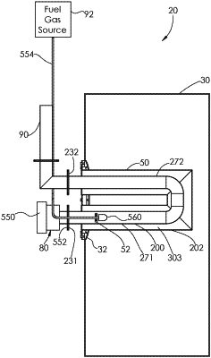
1. A coolant-filled heat exchanger for an oil treater, comprising:
an inner u-shaped tube having first, second, and third inner tube portions each having a first diameter, the first, second, and third inner tube portions defining an outer surface;
an outer u-shaped tube having first, second, and third outer tube portions each having a second diameter; the second diameter being greater than the first diameter, the first, second, and third outer tube portions defining an inner surface, the first, second, and third inner tube portions being disposed within the first, second, and third outer tube portions, respectively, an interior region being formed between the outer surface of the inner u-shaped tube and the inner surface of the outer u-shaped tube;
a mounting plate having first and second apertures extending therethrough, the first outer tube portion extending into the first aperture and being coupled to the mounting plate, the second outer tube portion extending into the second aperture and being coupled to the mounting plate;
a first ring-shaped end plate coupled to and between the outer surface of the first inner tube portion and the inner surface of the first outer tube portion to enclose and seal a first opening communicating with the interior region, the first ring-shaped end plate being disposed a first distance from an open end of the first inner tube portion; and
a second ring-shaped end plate coupled to and between the outer surface of the second inner tube portion and the inner surface of the second outer tube portion to enclose and seal a second opening communicating with the interior region, the second ring-shaped end plate being disposed the first distance from an open end of the second inner tube portion, the interior region being adapted to be filled with a coolant;
wherein the mounting plate is configured to be removably fixed to a storage tank of the oil treater such that the inner u-shaped tube and the outer u-shaped tube are at least partially located within the storage tank.
|