| CPC F23B 50/12 (2013.01) [A24B 3/12 (2013.01); F23B 30/00 (2013.01); F24B 13/04 (2013.01)] | 8 Claims |

|
1. A biomass burner, comprising:
a hopper;
a ventilating chamber;
a U-shaped fire box;
a feeding cylinder comprising an output end;
an auger;
a feeding motor comprising a driving wheel;
an ignition device;
an ignition motor;
a ventilation plate;
a first poking device;
a second poking device;
a first poking motor configured to drive the first poking device;
a second poking motor configured to drive the second poking device;
a first fixed plate; and
a second fixed plate;
wherein:
the hopper is disposed below the feeding cylinder;
the feeding cylinder is disposed through the ventilating chamber and the output end of the feeding cylinder extends into the U-shaped fire box;
the auger is disposed in the feeding cylinder and is driven by the feeding motor;
one end of the auger is provided with a driven gear, and the driven gear is meshed with the driving wheel of the feeding motor;
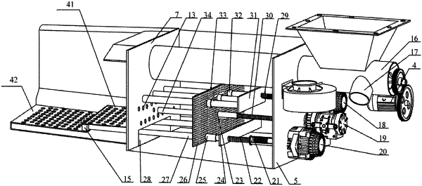
the ventilating chamber is in the shape of a box, and comprises an outer seal plate disposed on one side of the hopper, an inner seal plate disposed on one side of the U-shaped fire box, and a plurality of side plates;
the inner seal plate comprises a bottom ventilation hole, a horizontal air outlet, a first through hole, and a fuel outlet; the bottom ventilation hole is disposed on a lower end of the inner seal plate, and the ventilating chamber communicates with the U-shaped fire box through the bottom ventilation hole; the horizontal air outlet is disposed above the bottom ventilation hole, and the ventilating chamber further communicates with the U-shaped fire box through the bottom ventilation hole;
the ignition device is disposed in the ventilating chamber and lower than the feeding cylinder, and is driven by the ignition motor; and the ignition motor is disposed below the hopper;
the outer seal plate comprises a second through hole, and the ignition device comprises a threaded transmission rod and a fire rod; the threaded transmission rod is disposed through the second through hole, and one end of the threaded transmission rod is connected to the ignition device, and other end thereof is connected to the fire rod; the fire rod is disposed through the first through hole of the inner seal plate and extends into the U-shaped fire box; the output end of the feeding cylinder is disposed through the fuel outlet, and a fuel in the feeding cylinder is driven by the auger to fall into the U-shaped fire box through the fuel outlet;
the ventilation plate is disposed vertically fixedly on an inner wall of the ventilating chamber and lower than the feeding cylinder; the ventilation plate comprises a plurality of ventilation holes, and the fire rod is disposed through the ventilation plate;
the U-shaped fire box comprises a stepped base, and two sides of the stepped base are fixedly connected to two side walls of the U-shaped fire box, respectively; the stepped box comprises a plurality of vertical ventilation holes; a cavity is formed between the stepped base and a bottom wall of the U-shaped fire box, and communicates with the plurality of vertical ventilation holes and the bottom ventilation hole;
the stepped base comprises a first base and a second base; the first poking device and the second poking device are disposed in the ventilating chamber; the first poking device is disposed higher than the ignition device, and the second poking device is disposed lower than the ignition device;
the first poking motor is disposed outside the outer seal plate to drive the first poking device, and the first poking device comprises a first power conversion device, a first transmission screw rod, and a first poker; one end of the first power conversion device is connected to the first poking motor, and the other end thereof is connected to one end of the first transmission screw rod; the other end of the first transmission screw rod is connected to one side of the first fixed plate; the first poker is connected to the other side of the first fixed plate;
the ventilation plate comprises a first sliding sleeve, and the first poker is disposed through the first sliding sleeve; the inner seal plate comprises a third through hole, and the first poker is disposed through the third through hole and extends into the U-shaped fire box;
the second poking motor is disposed outside the outer seal plate to drive the second poking device, and the second poking device comprises a second power conversion device, a second transmission screw rod, and a second poker; one end of the second power conversion device is connected to the second poking motor, and the other end thereof is connected to one end of the second transmission screw rod; the other end of the second transmission screw rod is connected to one side of the second fixed plate; the second poker is connected to the other side of the second fixed plate;
the ventilation plate comprises a second sliding sleeve, and the second poker is disposed through the second sliding sleeve; the bottom ventilation hole is disposed below the first base; the second poker is disposed through the bottom ventilation hole and extends into the U-shaped fire box; and one end of the second poker is provided with a cross bar.
|