| CPC F21S 41/683 (2018.01) [F21S 41/148 (2018.01); F21S 41/27 (2018.01); F21S 41/32 (2018.01); F21S 41/43 (2018.01); F21S 45/40 (2018.01); F21S 41/147 (2018.01); F21S 41/36 (2018.01); F21S 41/39 (2018.01); F21S 41/395 (2018.01); F21S 41/689 (2018.01); F21S 41/692 (2018.01); F21S 45/48 (2018.01); F21W 2102/13 (2018.01)] | 9 Claims |
|
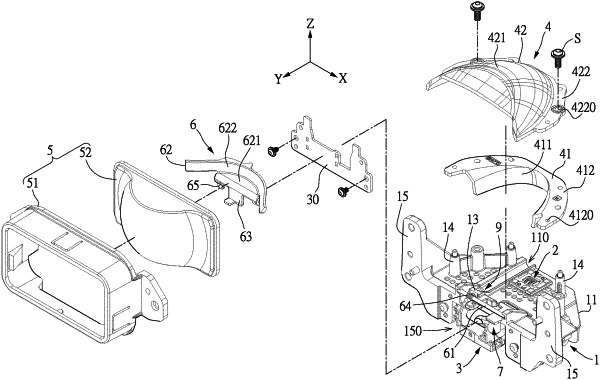
1. A vehicle lamp having a dipped and main beam headlight switching structure, comprising:
a heat-dissipating device having a carrier base; wherein the heat-dissipating device is provided with an adjusting groove and an adjusting screw seat, the adjusting groove has a semi-cylindrical shape and is recessed in the carrier base of the heat-dissipating device, and the adjusting groove is extended forward from a rear side of the heat dissipating device along one side of an LED light source, and wherein the adjusting screw seat is located in the adjusting groove;
the LED light source disposed on the carrier base of the heat-dissipating device;
an electromagnet disposed on the heat-dissipating device;
a light-reflecting assembly located above the LED light source;
a lens assembly located in front of the light-reflecting assembly, wherein the light-reflecting assembly is configured to reflect light emitted by the LED light source to form reflected light, and the lens assembly is configured to allow the light to pass therethrough;
a light-shaping plate rotatably disposed between the light-reflecting assembly and the lens assembly, wherein the light-shaping plate is pivotally disposed on the heat-dissipating device along a rotating shaft, the light-shaping plate has a force bearing portion formed under the rotating shaft, and the light-shaping plate is configured to be movably located at one of a first position and a second position; and
a driving rod disposed between the electromagnet and the light-shaping plate, wherein the electromagnet is configured to drive the driving rod to move the light-shaping plate to the first position or the second position, so as to change the reflected light to form near light or far light;
an adjusting rod being screwed to the adjusting screw seat of the heat-dissipating device, one side of the adjusting rod is exposed at the rear side of the heat-dissipating device for adjustment, and another side of the adjusting rod abuts against the force bearing portion of the light-shaping plate, wherein a length of the adjusting groove is longer than a length of the adjusting rod;
wherein the lens assembly has a frame and a lens, the lens is fixed on a front side of the frame, the frame is fixed on the heat-dissipating device, and an empty space is formed between the frame and the heat-dissipating device for accommodating components.
|