| CPC F16M 11/2078 (2013.01) [F16M 13/022 (2013.01); A61B 90/50 (2016.02)] | 13 Claims |
|
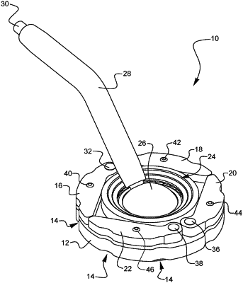
1. A torque enhancing apparatus, comprising:
a mounting assembly comprising:
a mounting arm extending from a first end to a second end; and
a ball disposed at the second end of the mounting arm, the ball having a first diameter;
a first socket comprising:
a first coupling portion having a first cylindrical surface, wherein at least a portion of the first cylindrical surface is threaded; and
a first receiving enclosure having one or more circumferential walls that extend along a first socket axis and a support wall that extends substantially transverse to the first socket axis, the first receiving enclosure configured to receive at least a portion of the ball of the mounting assembly such that a first portion of the ball contacts a portion of the support wall;
a second socket comprising:
a flange portion including a top surface that surrounds a first portion of a central aperture extending through the flange portion, the central aperture having a second diameter that is less than the first diameter;
an elongated first moment arm that extends from a first end to a second end, the first end being pivotably coupled to a first portion of the flange portion, the first moment arm configured to be pivoted between a retraced position and an extended position, wherein when the first moment arm is in the extended position, the second end extends beyond an outer perimeter edge defining the flange portion, and wherein when the first moment arm is in the retracted position, the second end does not extend beyond the outer perimeter edge defining the flange portion;
an elongated second moment arm that extends from a first end to a second end, the first end being pivotably coupled to a second portion of the flange portion, the second moment arm configured to be pivoted between a retraced position and an extended position, wherein when the second moment arm is in the extended position, the second end extends beyond the outer perimeter edge defining the flange portion, and wherein when the second moment arm is in the retracted position, the second end does not extend beyond the outer perimeter edge defining the flange portion; and
a cylindrical second coupling portion projecting from the flange portion, the second coupling portion comprising:
one or more inner surfaces that define a second portion of the central aperture;
a second socket engagement portion disposed at an end portion of the second coupling portion; and
a circumferential second cylindrical surface, wherein at least a portion of the second cylindrical surface is threaded, and wherein the threaded portion of the second cylindrical surface engages the threaded portion of the first cylindrical surface to displace the second socket between an engaged position and a disengaged position relative to the first socket, wherein:
(a) when the second cylindrical surface is rotated in a first rotational direction relative to the first cylindrical surface, the second socket engagement portion of the second socket displaces in a first linear direction towards a second portion of the ball until the second socket engagement portion contacts the second portion of the ball such that the second socket is in the engaged position in which the ball is fixed between the second socket engagement portion and the support wall of the first receiving enclosure of the first socket, and
(b) when the second cylindrical surface is rotated in a second rotational direction relative to the first cylindrical surface, the second socket engagement portion of the second displaces in a second linear direction away from the second portion of the ball until the second socket engagement portion is not in contact with the second portion of the ball such that the second socket is in the disengaged engaged position in which the ball is the rotatable relative to the first socket that thus the mounting arm is positionable relative to the first socket, and
wherein each of the first moment arm and the second moment arm are configured to be rotated from the retraced position to the extended position such that a force is configured to be applied by a user to the second end of each of the first moment arm and the second moment arm to rotate the second socket from the disengaged position to the engaged position.
|