| CPC F01D 25/30 (2013.01) [F01D 25/24 (2013.01); F05D 2220/31 (2013.01)] | 9 Claims |

|
1. A turbine comprising:
a rotor including:
a rotation shaft that rotates around an axis of the rotation shaft; and
blade rows on an outer peripheral surface of the rotation shaft that are separated from each other in a direction of the axis;
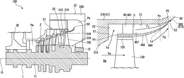
a casing covering an outer circumference of the rotor and that has a casing inner peripheral surface expanding radially outward toward downstream of the casing; and
an inner peripheral member body that:
extends over the casing inner peripheral surface of the casing, and forms:
an extraction port between an upstream side end of the inner peripheral member body and the casing inner peripheral surface, and
a discharge port between a downstream side end of the inner peripheral member body and the casing inner peripheral surface,
wherein the inner peripheral member body is separated in a radial direction of the rotor from a final stage blade row that is disposed on a most downstream side of the blade rows and faces at least a portion of the final stage blade row in the radial direction,
wherein the extraction port is disposed upstream of a downstream end of the final stage blade row,
wherein the discharge port is disposed downstream of the final stage blade row,
wherein the extraction port and the discharge port are in an annular shape centered on the axis, and
wherein a flow path cross-sectional area of the discharge port is smaller than a flow path cross-sectional area of the extraction port.
|