| CPC E04D 1/16 (2013.01) [E04D 1/365 (2013.01); E04D 3/06 (2013.01); F24S 25/613 (2018.05); H02S 20/23 (2014.12); H02S 20/25 (2014.12); E04D 2001/342 (2013.01); E04D 2001/3414 (2013.01); E04D 2001/3432 (2013.01)] | 15 Claims |

|
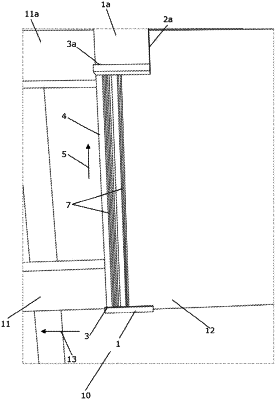
1. A system for mounting glass roof tiles on a roof construction, the system comprising:
a roof batten extending along a first longitudinal direction,
a S-shaped bracket defining a first U-shaped portion and a second U-shaped portion,
a sealing plate extending along a second longitudinal direction being transverse to the first longitudinal direction, and
two glass roof tiles arranged side by side along the first longitudinal direction,
wherein the first U-shaped portion of the S-shaped bracket is clamped onto the roof batten and retained in relation thereto solely by means of friction and gravity, and in that an end portion of the sealing plate and a lower end portion of each of the two glass roof tiles are snugly fit into the second U-shaped portion of the S-shaped bracket, such that the S-shaped bracket and the sealing plate overlap the respective lower end portions of the two glass roof tiles when the two glass roof tiles are arranged side by side along the first longitudinal direction, and such that the sealing plate and the two glass roof tiles are retained in relation to the S-shaped bracket solely by means of friction and gravity;
wherein the first U-shaped portion of the S-shaped bracket is defined by two mutually spaced wall sections and a connecting section interconnecting the wall sections, and
wherein each of the wall sections has a height not exceeding the height of the roof batten, so that each of the wall sections is in abutment with the roof batten along an entire height of the respective wall section.
|