| CPC E04B 1/167 (2013.01) [E04B 1/165 (2013.01); E04B 1/30 (2013.01); E04C 3/34 (2013.01)] | 3 Claims |

|
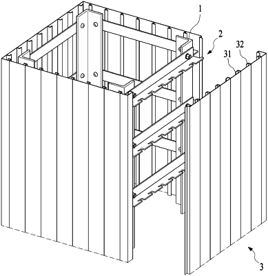
1. A combination structure of permanent forms (3) and a prefabricated steel assembly for a steel concrete composite member, the combination structure comprising:
the prefabricated steel assembly configured to build the steel concrete composite member and having a plurality of shape steel members (1) disposed on corners of the steel concrete composite member in such a manner as to be internally spaced apart from surfaces of the steel concrete composite member and a plurality of support bars (2) coupled to outer surfaces of the shape steel members (1) to connect neighboring shape steel members (1), each support bar (2) having a ‘L’-shaped section in such a manner as to allow one side leg (21) thereof to be fixedly coupled to the shape steel members (1); and
each permanent form (3) having a flat plate (31) configured to build an outer surface of the steel concrete composite member, protrusions (32) having ‘L’-shaped sections in such a manner as to protrude longitudinally from an inner surface of the flat plate (31), a bent corner portion (33) bent vertically from one side end of the flat plate (31) toward a neighboring member surface, and an outer protrusion (34) having a ‘L’-shaped section, protruding longitudinally from an inner end of the bent corner portion (33), and laid on top of a protrusion (32′) formed on an outermost position of the permanent form (3′) coupled to the neighboring member surface,
wherein each support bar (2) has a second side leg (22) having ‘L’-shaped locking holes (221) whose inlets are larger than widths of the protrusions (32) so as to insertedly lock the protrusions (32) thereinto, wherein corner stiffeners (4) are spaced apart from each other in a longitudinal direction thereof and are coupled to an inside surface of the bent corner portion (33), each corner stiffener (4) having a first extended portion (42) extended from a protrusion side end portion thereof in such a manner as to surround the protrusion (32) and a second extended portion (43) extended from an outer protrusion side end portion thereof in such a manner as to be inserted into an inside section of the outer protrusion (34) and fixed to the bent corner portion (33) by means of welding.
|