| CPC D21F 9/04 (2013.01) [D21B 1/061 (2013.01); D21B 1/32 (2013.01)] | 6 Claims |

|
1. A defibrating apparatus comprising:
a rotational body;
a plate shaped side wall to which the rotational body is rotatably coupled;
a defibrating chamber that is partially defined by the plate shaped side wall, in which the rotational body is stored, and in which a defibrated material is formed from a raw material containing fibers while the rotational body is rotated;
a circular annular wall fixed to the plate shaped side wall such that an interval is provided between the circular annular wall and the rotational body in a radial direction of the rotational body, the circular annular wall partially defining the defibrating chamber;
a discharge path arranged such that the circular annular wall is disposed between the discharge path and the defibrating chamber;
a plurality of through-holes provided in the circular annular wall, the discharge path communicating with the defibrating chamber via the plurality of through-holes, and receiving the defibrated material discharged from the defibrating chamber via the plurality of through-holes; and
a housing that forms the discharge path, a side wall of the housing extending in a circumferential direction of the circular annular wall and having an inner surface that defines the discharge path, the side wall of the housing contacting the circular annular wall;
the discharge path having a width in an axial direction of the rotational body, and extends in the circumferential direction of the circular annular wall,
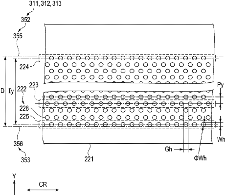
when a communication hole is any of the through-holes which interconnect the defibrating chamber and the discharge path, and a discharge path-side opening edge is any of opening edges, closest to the discharge path, of a plurality of communication holes each of which is the communication hole,
the circular annular wall having a communication hole group formed by a part of the plurality of communication holes, arranged at intervals in the circumferential direction, and
the communication hole group being provided at a position where the discharge path-side opening edge is overlapped with the inner surface as seen in the radial direction.
|