| CPC B67D 1/0802 (2013.01) [B67D 1/0462 (2013.01); B67D 1/1202 (2013.01); B67D 1/1272 (2013.01); B67D 2001/0824 (2013.01); B67D 2001/0825 (2013.01); B67D 2001/0827 (2013.01); B67D 2001/0828 (2013.01)] | 9 Claims |
|
1. A bag-in-keg container:
a container body (C);
a bag (J) within the container body;
a two-port valve (V) providing a first pathway (A) for gas and a second pathway (B) for liquid, said first pathway communicating with a space between the container (C) and the bag (J), and the second pathway communicating with the interior of the bag;
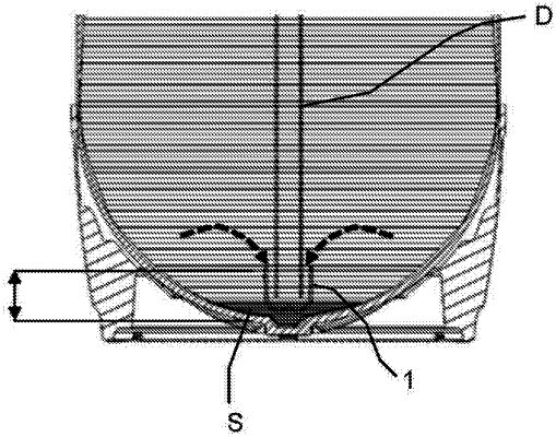
a container dip tube (D) within the bag connected to the second pathway (B) of the two port valve (V);
wherein
an end section of the container dip tube (D) has a flow terminal (1), said flow terminal defining a flow passage (8, 9) arranged to communicate with said liquid flow path and which includes a counter-flow portion (8) leading to an opening (4), whereby the direction of liquid flow through said opening (4) is reversed relative to the direction of liquid flow through said end section of the container dip tube (D);
wherein said flow terminal (1) includes an outer wall (2) to surround the end section of said dip tube, and wherein said counter-flow portion (8) is defined by a space between said outer wall and said end section;
wherein said flow terminal (1) includes an end wall (3) closing one end of said outer wall; and
wherein said flow terminal (1) includes retaining means (15) to connect the flow terminal to said end section of the dip tube and wherein said retaining means includes a pin (15) secured to said end wall (3).
|