| CPC B64D 33/02 (2013.01) [F01D 25/24 (2013.01); F02C 7/04 (2013.01)] | 20 Claims |
|
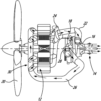
1. An aircraft engine comprising:
an exhaust conduit;
at least one combustion engine having an exhaust gas outlet fluidly connected to the exhaust conduit;
at least one gas turbine having a casing defining a radially outer limit of an annular gas path extending along and around a central axis, and at least one rotor having a shaft concentric to the central axis, a plurality of blades circumferentially interspaced from one another around the central axis and protruding radially from the shaft across the annular gas path; and
a gas turbine intake having a swirl housing having an inlet portion fluidly connecting the exhaust conduit, an annular outlet fluidly connecting the annular gas path, a swirl path extending circumferentially around the central axis from the inlet portion to a circumferential outlet, the circumferential outlet fluidly connected back into the inlet portion, and vanes located in the swirl housing, the vanes circumferentially interspaced from one another relative the central axis and located radially inwardly from the swirl path relative the central axis, the swirl path being free of the vanes.
|