| CPC B60G 15/062 (2013.01) [B60G 3/20 (2013.01); B60G 7/005 (2013.01); B60G 21/055 (2013.01); B60G 2204/416 (2013.01); B60G 2204/422 (2013.01); B60G 2206/427 (2013.01); B60G 2206/50 (2013.01); B60Y 2304/05 (2013.01)] | 6 Claims |
|
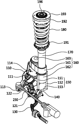
1. A strut suspension system configured to absorb impact and vibrations transferred to a vehicle body from a road surface through a wheel, the strut suspension system comprising:
a strut provided between the vehicle body and the wheel and to which a knuckle arm connecting a steering system of a vehicle to the wheel is connected to be relatively rotatable when the steering system performs steering;
a stabilizer link having one end connected to a stabilizer bar configured to increase roll rigidity of the vehicle body and the other end coupled to prevent the strut from rotating,
a control arm configured to support movement of the wheel is connected to a bottom of the knuckle arm with a ball joint as a medium, and
a support portion configured to connect and support the knuckle arm and the strut to be relatively rotatable,
wherein,
when the steering system performs steering, the knuckle arm and the wheel are rotated in a steering direction of the steering system, and the strut is fixed by the stabilizer link and prevented from rotating,
the stabilizer link and the stabilizer bar are separated from the knuckle arm and the control arm,
the stabilizer link is integrally coupled to the support portion,
the stabilizer link comprises a first coupling link coupled to one surface of the support portion, a second coupling link coupled to the other surface of the support portion, and a connection link having both ends integrally connected to the first coupling link and the second coupling link, respectively, and
a space through which a drive shaft configured to transfer torque to the wheel passes is formed below a second support member among the first coupling link, the second coupling link, and the connection link.
|