| CPC B60C 11/1204 (2013.01) [B60C 11/1263 (2013.01); B60C 2011/0341 (2013.01); B60C 2011/0372 (2013.01); B60C 2011/0381 (2013.01); B60C 2011/1209 (2013.01); B60C 2011/1213 (2013.01)] | 17 Claims |

|
1. A tire comprising:
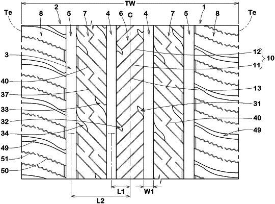
a tread portion comprising a plurality of circumferential grooves extending continuously in a tire circumferential direction and a first land portion divided by the circumferential grooves,
the first land portion having a first circumferential edge, a second circumferential edge and a ground contacting surface therebetween,
the ground contacting surface being provided with a plurality of inclined sipes inclined in a first direction with respect to a tire axial direction,
the plurality of inclined sipes comprising first inclined sipes and second inclined sipes arranged adjacently in the tire circumferential direction,
each of the first inclined sipes comprising a first deep-bottom portion located on the first circumferential edge side, and a first shallow-bottom portion located on the second circumferential edge side and having a smaller depth than the first deep-bottom portion,
each of the second inclined sipes comprising a second deep-bottom portion located on the second circumferential edge side, and a second shallow-bottom portion located on the first circumferential edge side and having a smaller depth than the second deep-bottom portion, and
each second deep-bottom portion being arranged so as to overlap a projection region in which a respective first deep-bottom portion is expanded parallel to the tire axial direction,
wherein the first land portion further comprises
first short grooves extending from the first circumferential edge and terminating within the first land portion,
second short grooves extending from the second circumferential edge and terminating within the first land portion, and
connecting sipes extending from the first short grooves to the second short grooves,
wherein a maximum depth of the connecting sipes is smaller than a maximum depth of the first deep-bottom portions and a maximum depth of the second deep-bottom portions.
|