| CPC B41J 2/155 (2013.01) [B41J 2/1433 (2013.01); B41J 2002/14491 (2013.01)] | 12 Claims |

|
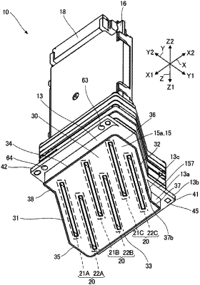
1. A liquid ejecting head that is arranged in a first direction and held by a holding member to form a line head, the liquid ejecting head comprising:
an ejection surface including head chips configured to eject a liquid; and
a first positioning portion and a second positioning portion that are respectively disposed toward a second direction with respect to the ejection surface and are positioned with respect to the holding member, the second direction being orthogonal to the first direction when the ejection surface is viewed in a normal direction of the ejection surface, wherein
when the ejection surface is viewed in the normal direction of the ejection surface, an outer shape of the liquid ejecting head has:
a first edge and a second edge separated from each other in the first direction and extending along a third direction parallel to the ejection surface and inclined with respect to the first direction and the second direction; and
one end portion and the other end portion that form both end portions in the second direction,
when the ejection surface is viewed in the normal direction of the ejection surface, the first positioning portion is not overlapped with a virtual parallelogram having a first virtual side contacting the first edge and extending along the third direction, a second virtual side contacting the second edge and extending along the third direction, a third virtual side contacting the one end portion and extending along the first direction, and a fourth virtual side contacting the other end portion and extending along the first direction,
the first positioning portion and the second positioning portion are arranged in the first direction and are separated from each other in the first direction, and
each of the first and second positioning portions is either an opening, a recess, or a ridge.
|