| CPC B23Q 7/04 (2013.01) [B25J 9/101 (2013.01); B25J 9/102 (2013.01)] | 3 Claims |

|
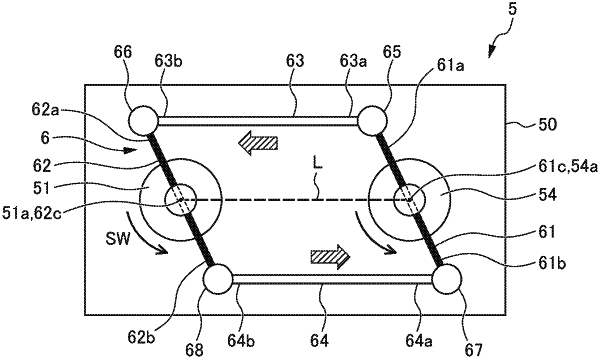
1. A drive mechanism of a transfer tool, the drive mechanism configured to drive a swing axis which is provided to the transfer tool that transfers a workpiece, and tilts the workpiece relative to the transfer tool, the drive mechanism comprising:
a motor;
a speed reducer including an output shaft arranged in parallel to the swing axis and configured to reduce a speed of rotation of the motor; and
a link mechanism configured to couple the swing axis with the output shaft,
wherein the link mechanism includes
a first link portion fixed directly and physically connected to the output shaft at a middle portion in a length direction of the first link portion to move with a rotation of the output shaft;
a second link portion fixed to the swing axis at a middle portion in a length direction of the second link portion;
a third link portion that couples one end portion of the first link portion and one end portion of the second link portion with each other in a rotatable manner; and
a fourth link portion that couples another end portion of the first link portion and another end portion of the second link portion with each other in a rotatable manner,
wherein the first link portion and the second link portion are arranged in parallel to each other,
wherein the third link portion and the fourth link portion are arranged in parallel to a line segment linking a central axis of the output shaft with a central axis of the swing axis such that the speed of rotation of the motor is reduced by the speed reducer, and the rotation of the output shaft of the speed reducer is directly transmitted to the swing axis via the first, second, third, and fourth link portions of the link mechanism.
|