| CPC B04C 5/28 (2013.01) [B01D 19/0057 (2013.01); B04C 5/04 (2013.01); B04C 5/13 (2013.01); B04C 5/181 (2013.01)] | 34 Claims |

|
1. A separator apparatus comprising:
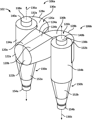
a first cyclone device comprising:
a first inlet section having a first end and a second end, wherein a cross-sectional area of the first inlet section increases from the first end to the second end;
a first scroll comprising a curved member;
a first barrel centered on a first axis, the barrel defining a first interior volume, the first barrel having a diameter, a first end, and a second end, wherein the scroll is attached to the first inlet section and to the first barrel, and connects the first inlet section to the first barrel;
a first vortex finder comprising a first vortex tube arranged concentrically on the first axis in the first barrel on the first axis adjacent the first end of the first barrel; and
a first underflow portion comprising a first conical member and a first underflow body, the first underflow portion defining a first annular gap in fluid connection with the first interior volume;
a second cyclone device comprising:
a second inlet section having a first end and a second end, wherein a cross-sectional area of the second inlet section increases from the first end to the second end;
a second scroll;
a second barrel centered on a second axis, the barrel defining a second interior volume, the second barrel having a diameter, a first end, and a second end, wherein the scroll connected the second inlet section to the second barrel;
a second vortex finder having a second vortex tube arranged on the second axis concentrically in the second barrel on the axis adjacent the first end of the second barrel; and
a second underflow portion having a second conical member and a second underflow cylinder, the second underflow portion defining a second annular gap in fluid connection with the second interior volume; and
an intake nozzle fluidly connected to the first inlet section and second inlet section.
|