| CPC A61M 25/00 (2013.01) [A61B 18/1492 (2013.01); A61M 25/008 (2013.01); A61M 25/0054 (2013.01); A61M 25/0067 (2013.01); A61M 25/0068 (2013.01); A61M 25/0074 (2013.01); A61M 25/0082 (2013.01); A61M 25/0133 (2013.01); A61M 25/0136 (2013.01); A61M 25/0147 (2013.01); A61B 2017/00323 (2013.01); A61B 2018/00196 (2013.01); A61B 2018/00357 (2013.01); A61B 2018/00577 (2013.01); A61B 2018/00839 (2013.01); A61B 2018/1407 (2013.01); A61M 2025/0163 (2013.01)] | 12 Claims |
|
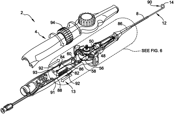
1. A catheter comprising:
a longitudinally-extending catheter shaft comprising a proximal end portion and a distal end deflectable portion, wherein the distal end deflectable portion includes a loop member;
a handle attached to the proximal end portion of the catheter shaft;
a deflection mechanism positioned inside the handle and including a pull wire for deflecting the distal end deflectable portion of the catheter shaft; and
a loop member adjustment mechanism for adjusting a diameter of the loop member, the loop member adjustment mechanism comprising:
a single loop member pull wire, wherein a distal end of the single loop member pull wire is attached to the loop member;
a sliding member, located within the handle, wherein the sliding member is configured to translate within the handle without rotating within the handle, wherein the sliding member comprises a first side including first gears, a second, opposite side including second gears, and a planar surface extending between the first side and the second side, and wherein a proximal end of the single loop member pull wire is directly coupled to a pin included in the sliding member, a portion of the single loop member pull wire extending across the planar surface of the sliding member; and
a rotatable knob located on an exterior of the handle and circumscribing the sliding member, the rotatable knob interfacing with the sliding member such that rotation of the rotatable knob adjusts the diameter of the loop member by causing the sliding member, pin, and proximal end of the single loop member pull wire to translate within the handle, wherein to interface with the sliding member, an underside of the rotatable knob comprises third gears that engage both the first gears formed on the first side of the sliding member and the second gears formed on the second side of the sliding member.
|