| CPC A61L 2/10 (2013.01) [A61L 2202/11 (2013.01); A61L 2202/122 (2013.01)] | 20 Claims |

|
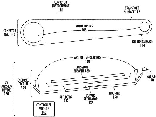
1. An ultraviolet (“UV”) emission device for a conveyor system, the UV emission device comprising:
a housing that is configured to attach to a frame of the conveyor system, the frame supporting a moveable surface of the conveyor system, such that a return surface of the moveable surface is located within an interior cavity of the frame, wherein the housing is further configured to attach to the frame within the interior cavity,
the housing having a moveable portion and a fixed portion, wherein:
the fixed portion and the moveable portion are configured to form a UV emission zone within the interior cavity, wherein the UV emission zone is defined by the return surface, the fixed portion, and the moveable portion,
the fixed portion is configured to contact the return surface within the interior cavity, wherein a first longitudinal edge of the fixed portion extends along the return surface at a first location on the frame and a second longitudinal edge of the fixed portion extends along the return surface at a second location on the frame, the first and second longitudinal edges defining edges of the UV emission zone against the return surface, and
the moveable portion being configured to fit against an access opening of the fixed portion, such that, in an open position of the moveable portion, the UV emission zone is accessible via the access opening and, in a closed position of the moveable portion, the UV emission zone is inaccessible via the access opening,
wherein at least one panel edge of the moveable portion is configured to extend along a barrier edge of the access opening;
an energy emission element arranged within the UV emission zone;
a barrier bracket arranged along the panel edge of the moveable portion, the barrier bracket having a first position and a second position; and
an absorptive barrier supported via the barrier bracket, wherein the absorptive barrier is configured to contact, along the panel edge of the moveable portion, the barrier edge of the access opening, wherein:
in the first position of the barrier bracket, the absorptive barrier contacts the barrier edge of the access opening and the barrier bracket activates an interlock switch, and
in the second position of the barrier bracket, the barrier bracket deactivates the interlock switch.
|