| CPC A61F 2/442 (2013.01) [A61F 2/4455 (2013.01); A61F 2/4465 (2013.01); A61F 2/4611 (2013.01); A61F 2002/2817 (2013.01); A61F 2002/2835 (2013.01); A61F 2002/3008 (2013.01); A61F 2002/3082 (2013.01); A61F 2002/30266 (2013.01); A61F 2002/30304 (2013.01); A61F 2002/30538 (2013.01); A61F 2002/30593 (2013.01); A61F 2002/30777 (2013.01); A61F 2002/30779 (2013.01); A61F 2002/30785 (2013.01); A61F 2002/30843 (2013.01); A61F 2002/30879 (2013.01); A61F 2002/30883 (2013.01); A61F 2002/4627 (2013.01)] | 13 Claims |
|
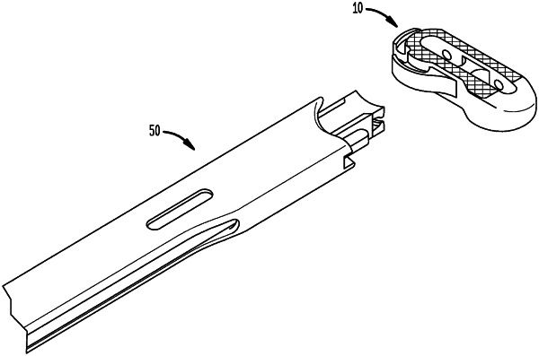
1. A surgical method comprising:
engaging a tool to an interface of an implant, the interface defining a rail having a neck portion connected to and extending away from a rear end of a body of the implant, the rail further having a lip portion connected to the neck portion, the lip portion being wider than the neck portion in a direction extending between top and bottom surfaces of the body;
moving the tool along an insertion direction to insert the implant at least partially into an intervertebral disc space between two adjacent vertebrae; and
sliding the tool along the rail from a position at a rear-facing surface of the body to a position at a posterior-facing surface of the body while moving the tool further along the insertion direction to allow the implant to rotate with respect to the insertion direction within the intervertebral disc space.
|