| CPC A61B 17/072 (2013.01) [A61B 2017/0042 (2013.01); A61B 2017/00398 (2013.01); A61B 2017/07264 (2013.01); A61B 2017/07271 (2013.01); A61B 2017/07278 (2013.01); A61B 2017/07285 (2013.01); A61B 2017/2927 (2013.01); A61B 2017/2933 (2013.01); A61B 2017/2943 (2013.01); A61B 2017/2946 (2013.01); A61B 2034/302 (2016.02)] | 24 Claims |

|
1. A surgical stapling assembly, comprising:
a first jaw;
a second jaw movable relative to said first jaw;
a firing screw; and
a firing assembly configured to be actuated by said firing screw through a firing stroke, wherein said firing assembly comprises:
a body portion, comprising:
a first cam configured to engage said first jaw during the firing stroke;
a second cam configured to engage said second jaw during the firing stroke;
a first passage configured to non-threadably receive said firing screw, wherein said first passage defines a first longitudinal axis; and
a slot defined in said body portion comprising a distal surface, wherein said distal surface comprises a driven surface; and
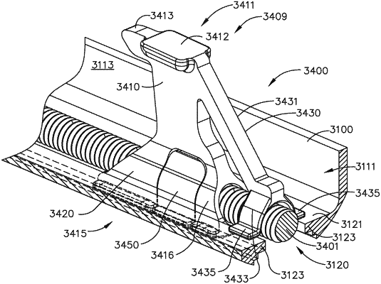
a nut configured to transmit a drive force from said firing screw to said body portion during the firing stroke, wherein said nut is position within said slot, wherein said nut comprises:
a driven portion comprising a threaded passage threadably coupled to said firing screw, wherein said threaded passage defines a second longitudinal axis, wherein a variable clearance is defined between said driven portion and said body portion; and
a driving portion extending from said driven portion, wherein said driving portion is configured to transmit the drive force to said driven surface off center from said firing screw during the firing stroke, wherein said variable clearance comprises a first longitudinal gap width between said nut and said distal surface and a second longitudinal gap width greater than said first longitudinal gap width between said nut and said distal surface when said first longitudinal axis and said second longitudinal axis are coaxial, said second longitudinal gap spaced further from said first longitudinal axis than said first longitudinal gap, thereby defining the variable clearance.
|