| CPC A61B 17/068 (2013.01) [A61B 17/064 (2013.01); A61B 17/0643 (2013.01); A61B 17/0644 (2013.01); A61B 17/0682 (2013.01); A61B 17/0686 (2013.01); A61B 17/072 (2013.01); A61B 17/07207 (2013.01); A61B 17/07292 (2013.01); A61B 17/105 (2013.01); A61B 17/115 (2013.01); A61B 17/1114 (2013.01); A61B 17/1155 (2013.01); A61B 17/135 (2013.01); F02D 11/105 (2013.01); F02D 31/002 (2013.01); F02D 35/025 (2013.01); F02D 41/042 (2013.01); F02D 41/065 (2013.01); F02D 41/3094 (2013.01); F02N 11/0814 (2013.01); A61B 90/39 (2016.02); A61B 2017/00004 (2013.01); A61B 2017/00398 (2013.01); A61B 2017/00526 (2013.01); A61B 2017/00734 (2013.01); A61B 2017/00818 (2013.01); A61B 2017/00893 (2013.01); A61B 2017/00898 (2013.01); A61B 2017/07228 (2013.01); A61B 2017/07257 (2013.01); A61B 2017/07264 (2013.01); A61B 2017/2905 (2013.01); A61B 2017/2927 (2013.01); A61B 2017/2929 (2013.01); A61B 2017/320052 (2013.01); A61B 2090/031 (2016.02); A61B 2090/037 (2016.02); A61F 5/0086 (2013.01); F01P 5/04 (2013.01); F01P 5/10 (2013.01); F01P 7/08 (2013.01); F01P 7/16 (2013.01); F01P 7/162 (2013.01); F01P 2023/08 (2013.01); F01P 2031/30 (2013.01); F01P 2037/02 (2013.01); F02D 41/3809 (2013.01); F02D 41/401 (2013.01); F02D 41/402 (2013.01); F02D 2011/102 (2013.01); F02D 2011/104 (2013.01); F02D 2041/0095 (2013.01); F02D 2041/389 (2013.01); F02D 2200/501 (2013.01); F02D 2200/602 (2013.01); F02D 2200/604 (2013.01); F02N 19/02 (2013.01); Y02T 10/40 (2013.01); Y10S 227/902 (2013.01)] | 18 Claims |

|
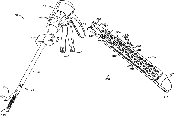
13. A surgical staple cartridge, comprising:
a cartridge body, comprising:
a proximal end;
a distal end;
a longitudinal slot extending from the proximal end toward the distal end, wherein the longitudinal slot defines a longitudinal cartridge axis, wherein a first cartridge side of the cartridge body is on a first lateral side of the longitudinal slot and a second cartridge side of the cartridge body is on a second lateral side of the longitudinal slot;
a longitudinal row of first staple cavities defined in the first cartridge side, wherein each first staple cavity comprises:
a first proximal end;
a first distal end; and
a first cavity axis extending between the first proximal end and the first distal end; and
a longitudinal row of second staple cavities defined in the first cartridge side, wherein the longitudinal row of first staple cavities is positioned intermediate the longitudinal slot and the longitudinal row of second staple cavities, and wherein each second staple cavity comprises:
a second proximal end;
a second distal end; and
a second cavity axis extending between the second proximal end and the second distal end, wherein the second cavity axis extends at a transverse angle relative to the longitudinal cartridge axis and at a transverse angle relative to the first cavity axis;
a plurality of staples; and
a ramp movable from a proximal unfired position to a distal fired position during a staple firing stroke, wherein the ramp is configured to lift the staples out of the cartridge body during the staple firing stroke.
|