US 11,849,835 B2
Cleaning devices having feedback between different cleaning states
William Harrington, Charlestown, RI (US); James M. Buckley, New Hartford, CT (US); Robert F. Smith, Waterbury, CT (US); and Paul Adams, Monroe, CT (US)
Filed by Unger Marketing International, LLC, Bridgeport, CT (US)
Filed on Oct. 6, 2020, as Appl. No. 17/064,156.
Application 17/064,156 is a continuation of application No. 14/668,535, filed on Mar. 25, 2015, granted, now 10,827,822.
Application 14/668,535 is a continuation in part of application No. 29/496,201, filed on Jul. 10, 2014, granted, now D771392, issued on Nov. 15, 2016.
Application 29/496,201 is a continuation in part of application No. 29/485,955, filed on Mar. 25, 2014, granted, now D744243, issued on Dec. 1, 2015.
Application 29/485,955 is a continuation in part of application No. 29/485,950, filed on Mar. 25, 2014, granted, now D744242, issued on Dec. 1, 2015.
Application 29/485,950 is a continuation in part of application No. 29/485,939, filed on Mar. 25, 2014, granted, now D744760, issued on Dec. 8, 2015.
Application 29/485,939 is a continuation in part of application No. 29/485,938, filed on Mar. 25, 2014, granted, now D743703, issued on Nov. 24, 2015.
Prior Publication US 2021/0015246 A1, Jan. 21, 2021
This patent is subject to a terminal disclaimer.
Int. Cl. A46B 5/00 (2006.01); A46B 15/00 (2006.01); A46B 5/02 (2006.01); A46B 9/06 (2006.01)
CPC A46B 5/0075 (2013.01) [A46B 5/0054 (2013.01); A46B 5/0083 (2013.01); A46B 5/021 (2013.01); A46B 9/06 (2013.01); A46B 15/004 (2013.01); A46B 15/0046 (2013.01)] 19 Claims
OG exemplary drawing
 
1. A cleaning device for cleaning a surface to be cleaned, comprising:
a handle;
a first member having a first cleaning surface;
a second member coupled to the handle and having a second cleaning surface; and
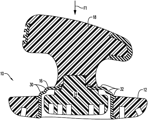
a deflection member coupled between the first member and the second member to couple the first member to the second member, the deflection member comprising at least one arm extending between the first member and the second member, wherein the at least one arm defines a first fulcrum point between the at least one arm and the first member and a second fulcrum point between the at least one arm and the second member, wherein the first and second members pivot relative to each other about the first and second fulcrum points,
wherein the deflection member comprises an annular structure defining an interior cavity, wherein the second member is arranged within the interior cavity defined by the annular structure, and the first member is arranged external to the deflection member, and
wherein, in response to a force applied to the handle by a user, the deflection member is configured to deform from a first shape to a second shape to provide feedback to the user.