| CPC A41D 13/0156 (2013.01) [A41D 31/285 (2019.02); B29C 43/003 (2013.01); B29C 43/021 (2013.01); B29C 43/36 (2013.01); B32B 3/02 (2013.01); B32B 3/08 (2013.01); B32B 5/024 (2013.01); B32B 5/026 (2013.01); B32B 5/26 (2013.01); B32B 27/08 (2013.01); B32B 27/12 (2013.01); B32B 27/32 (2013.01); B32B 27/40 (2013.01); B32B 38/185 (2013.01); B29C 2793/009 (2013.01); B32B 5/18 (2013.01); B32B 2037/1215 (2013.01); B32B 2262/0207 (2013.01); B32B 2262/0276 (2013.01); B32B 2266/025 (2013.01); B32B 2266/08 (2013.01); B32B 2305/02 (2013.01); B32B 2307/558 (2013.01); B32B 2571/00 (2013.01); B32B 2601/00 (2013.01); Y10T 156/1077 (2015.01)] | 14 Claims |

|
1. A method of manufacturing a flexible, impact-resistant pad comprising the steps of
providing a sheet of an impact-absorbing material;
cutting the sheet to provide a piece thereof with a profile required for the pad;
cutting the piece into a plurality of spaced, separate elements:
retaining said plurality of spaced, separate elements within the profile required for the pad;
providing a first, flexible layer of material;
bonding one side of the first, flexible layer of material to the spaced, separate elements;
at least part of an edge of the pad being streamlined by the following additional steps:
providing a contoured mould tool defining a recess that has a three dimensional shape complementary to a shape required on one side of the pad and that has a streamlined edge around at least part of its periphery;
heating the impact-absorbing material of the spaced, separate elements or the mould tool; and
pressing the mould tool into the impact-absorbing material of the spaced, separate elements to mould the impact-absorbing material of the spaced, separate elements on one side to define the shape that is required;
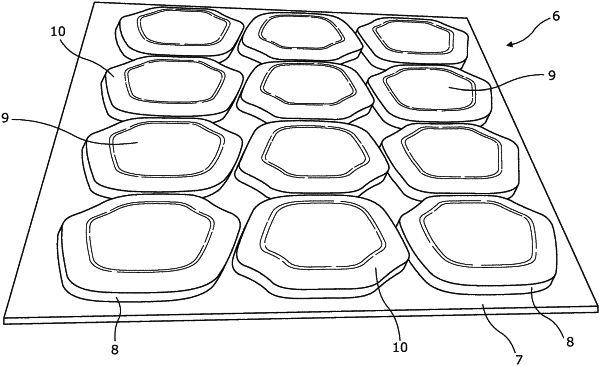
wherein the piece with the profile required for the pad is cut into the plurality of spaced, separate elements using a cutter which is pressed into the impact-absorbing material of the piece to cut therethrough, the cutter being adapted by the presence of ejectors that make the spaced, separate elements stand proud of a surface of the cutter;
wherein the cutter comprises a plurality of cutter blades each with a polygonal or closed curve profile that are mounted on a board, the ejectors comprising blocks located within each of the cutter blades that each define an exposed surface at a level higher, relative to the cutter blades, than a level of the board surrounding the cutter blades; and
wherein an overall profile made by the cutter blades is similar to the profile required for the pad and the ejectors of the cutter that act on the elements around the periphery of the pad, the spaced, separate elements located around a periphery of the pad each form a peripheral element and the ejectors of the cutter that act on the peripheral elements eject the peripheral elements to a greater extent than the ejectors acting on other spaced, separate elements, of the spaced, separate elements, whereby an uppermost surface collectively defined by all of the spaced, separate elements standing proud of the surface of the cutter is substantially planar.
|