| CPC A01D 61/02 (2013.01) [A01D 61/006 (2013.01); A01D 34/14 (2013.01)] | 21 Claims |

|
1. A crop harvesting header comprising:
a main frame structure extending across a width of the header for movement in a forward direction generally at right angles to the width across ground including a crop to be harvested;
an attachment member for attachment of the main frame structure to a feeder house of a harvester;
a cutter bar arranged to move over the ground in a cutting action and carrying a cutter knife operable for cutting the crop as the header is moved forwardly across the ground for depositing the crop onto the table;
a draper comprising a draper belt mounted on rollers generally parallel to the forward direction so that an upper run of the draper belt carries the crop transverse to the forward direction to a discharge end of the draper belt;
the draper belt having a front edge adjacent the cutter bar and a rear edge;
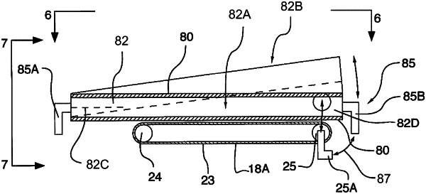
the rollers including a discharge end roller at the discharge end and an outer end roller at the end opposite the discharge end, each having a longitudinal roller axis;
the draper belt being wrapped around the discharge roller and around the outer end roller with a front end of each of the discharge and outer rollers at or adjacent the front edge of the belt and a rear end of the discharge and outer rollers at or adjacent the rear edge;
a first support arrangement supporting the front and the rear ends of the outer end roller;
a second support arrangement supporting the front and the rear ends of the discharge end roller;
the first and second support arrangements being mounted so that at least the rear end of the discharge end roller is movable in an upward and downward direction relative to the rear end of the outer end roller so that the discharge end roller has an operating position in which the axis of the discharge end roller is at an angle to a plane along the draper containing the axis of the outer end roller.
|