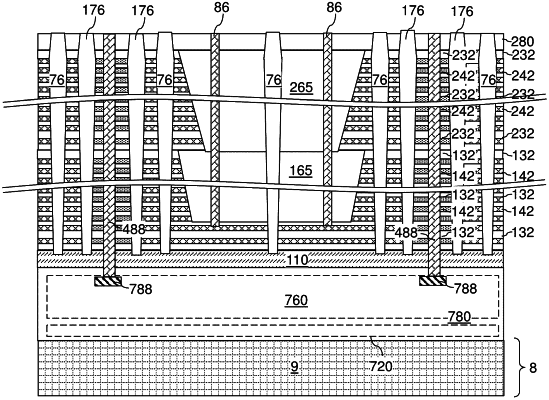
| CPC H10B 43/50 (2023.02) [H01L 23/5226 (2013.01); H01L 23/562 (2013.01); H10B 41/27 (2023.02); H10B 41/50 (2023.02); H10B 43/27 (2023.02)] | 3 Claims |

|
1. A three-dimensional memory device, comprising:
alternating stacks of insulating layers and electrically conductive layers located over a substrate, wherein the alternating stacks are laterally spaced apart from each other by backside isolation assemblies that laterally extend along a first horizontal direction; and
memory stack structures that vertically extend through a respective one of the alternating stacks, and wherein each of the memory stack structures comprises a respective vertical semiconductor channel and a respective vertical stack of memory elements,
wherein:
each of the backside isolation assemblies comprises a laterally alternating sequence of backside dielectric isolation walls and backside support pillar structures;
the backside dielectric isolation walls have a respective pair of lengthwise sidewalls that are parallel to the first horizontal direction and laterally spaced apart along a second horizontal direction that is perpendicular to the first horizontal direction;
the backside support pillar structures contact indented sidewalls of a respective one of the alternating stacks that are laterally recessed along the second horizontal direction relative to a straight vertical plane that includes interfaces between the backside dielectric isolation walls and the respective one of the alternating stacks in the horizontal cross-sectional view;
each of the backside support pillar structures vertically extends at least between a first horizontal plane including bottommost surfaces of the alternating stacks and a second horizontal plane including topmost surfaces of the alternating stacks;
each of the backside dielectric isolation walls vertically extends at least between the first horizontal plane and the second horizontal plane;
each of the backside dielectric isolation walls has the respective pair of lengthwise sidewalls that are laterally spaced apart along the second horizontal direction by a uniform width in a horizontal cross-sectional view;
each of the backside support pillar structures has a lateral extent along the second horizontal direction that is greater than the uniform width; and
each of the backside support pillar structures has a horizontal cross-sectional shape that includes:
a pair of lateral protrusion regions that protrude outward along the second horizontal direction; and
a pair of lateral recess regions that are recessed inward along the first horizontal direction.
|