| CPC H02K 15/0442 (2013.01) [B21F 3/04 (2013.01); H02K 15/045 (2013.01); H02K 15/0435 (2013.01)] | 8 Claims |

|
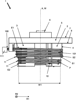
1. A winding device (50) having a coil former (1), for winding conductor wire (100) so as to form coil windings (101), which has a coil former front part (2) and a coil former rear part (3), wherein the coil former front part (2) and the coil former rear part (3) by way of a circumferential face (4) define for the conductor wire (100) a helical winding path (P) about a helix axis (W) and which coil former (1) is mounted on a rotary drive (51), and having a drawing-in tool (60) which has a flat ring-shaped member formed from drawing-in lamellas (61) which are aligned so as to be parallel and geodetically vertical, wherein the coil former (1) and the drawing-in tool (60) are mounted so as to be mutually movable in such a manner that a coil winding (101) that is wound from conductor wire (100) on the coil former (1) is capable of being placed from above about one or part of the drawing-in lamellas (61);
the winding device (50) being configured for rotating a placing pattern of a plurality of parallel conductor wires (100) by 180 degrees or a multiple thereof after each half or full revolution of the coil former (1), such that twists in the coil winding thus produced are positioned outside a drawing-in groove on a stator when drawing-in the coil winding into the drawing-in groove,
and wherein said coil former (1) has a wire infeed installation for a plurality of conductor wires (100) by way of which a first part of the plurality of conductor wires (100) is capable of being deposited so as to be mutually parallel in a first layer (S1) on the winding path (P) and simultaneously a second part of the plurality of conductor wires (100) is capable of being deposited so as to be mutually parallel in a second layer (S2) on the first layer (S1).
|