| CPC H02J 50/12 (2016.02) [H02J 5/00 (2013.01); H02J 50/502 (2020.01); H02J 50/90 (2016.02); H01F 38/00 (2013.01)] | 4 Claims |

|
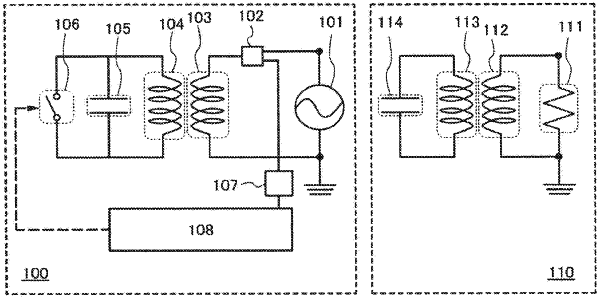
1. A power feeding device comprising:
a housing having a power supply surface and an opposite surface;
an electromagnetic coupling coil;
a resonance coil;
a switch electrically connected to the resonance coil;
a directional coupler electrically connected to the electromagnetic coupling coil;
a power source electrically connected to the electromagnetic coupling coil; and
a control circuit,
wherein the housing encloses the electromagnetic coupling coil, the resonance coil, the switch, the directional coupler, the power source and the control circuit,
wherein the control circuit is configured to turn on the switch to make the resonance coil short circuiting and to turn off the switch to make the resonance coil opened,
wherein the power feeding device is configured:
to conduct power feeding via the electromagnetic coupling coil using an electromagnetic coupling method when the switch is turned on; and
to conduct power feeding using a resonance method via the resonance coil when the switch is turned off,
wherein the electromagnetic coupling coil and the resonance coil are arranged to face each other,
wherein the power supply surface and the opposite surface face each other interposing the electromagnetic coupling coil and the resonance coil therebetween,
wherein the electromagnetic coupling coil is placed closer than the resonance coil to the power supply surface,
wherein the resonance coupling coil is placed closer than the electromagnetic coupling coil to the opposite surface, and
wherein the opposite surface is placed on an installation location by putting on a floor of the installation location or by fixing on a surface of the installation location, such that the electromagnetic coupling coil is arranged to be closer than the resonance coil to a power receiving device being wirelessly fed power by the power feeding device.
|