| CPC G06F 3/0421 (2013.01) [G01V 8/20 (2013.01); G06F 3/017 (2013.01); G06F 3/0416 (2013.01); G06F 2203/04108 (2013.01)] | 10 Claims |

|
1. A proximity sensor, comprising:
a circuit board;
a plurality of light emitters mounted on said circuit board;
a plurality of light detectors mounted on said circuit board;
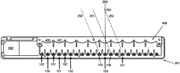
two stacked lenses, positioned above said light emitters and said light detectors, comprising an extruded cylindrical lens and a Fresnel lens array, wherein each of said emitters, when activated, projects a light beam through said two stacked lenses along a common projection plane, wherein a reflective object located in the common projection plane above said two stacked lenses reflects light projected at the reflective object from one or more of said emitters to one or more of said detectors, and wherein each emitter-detector pair, comprising one of said emitters and one of said detectors, when synchronously activated, is expected to generate a greater detection signal at the activated detector, when the reflective object is located at a specific 2D location in the common projection plane corresponding to the emitter-detector pair, than when the reflective object is located at any other location in the common projection plane; and
a processor connected to said emitters and to said detectors, sequentially activating each of said emitters and synchronously co-activating one or more of said detectors, and identifying a location of the reflective object in the common projection plane, based on amounts of light detected by the detector of each synchronously activated emitter-detector pair, wherein said processor is configured (i) to generate a first vector, the components of which correspond to the emitters, the components comprising, for each emitter, a sum of values corresponding to amounts of light detected by the detector of each synchronously activated emitter-detector pair having that emitter, (ii) to generate a second vector, the components of which correspond to distances from the sensor, the components comprising a sum of values corresponding to amounts of light detected by the detector of each synchronously activated emitter-detector pair whose corresponding specific 2D location is the same distance from the sensor, and (iii) to calculate at least one member of the group consisting of movement, velocity, size and location of the reflective object, along a first dimension of the common projection plane, based on the first vector, and along a second dimension of the common projection plane, based on the second vector.
|