| CPC G06F 1/08 (2013.01) [G01R 25/00 (2013.01); G06F 1/14 (2013.01); H03M 1/82 (2013.01); H03K 5/00 (2013.01); H03K 2005/00058 (2013.01); H03M 1/00 (2013.01)] | 17 Claims |

|
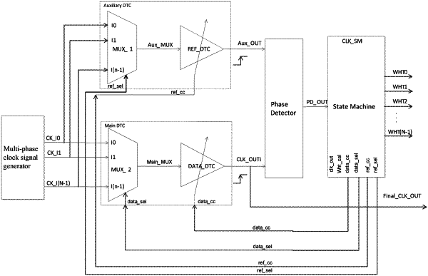
1. A multi-phase clock signal phase difference detection and calculation circuit, comprising:
an auxiliary digital-to-time conversion circuit;
a main digital-to-time conversion circuit;
a phase detector,
wherein an output terminal of the auxiliary digital-to-time conversion circuit and an output terminal of the main digital-to-time conversion circuit are respectively connected to an input terminal of the phase detector; and
a state machine,
wherein an output terminal of the phase detector is connected to an input terminal of the state machine,
wherein an output terminal of the state machine is connected to a control terminal of the auxiliary digital-to-time conversion circuit and a control terminal of the main digital-to-time conversion circuit,
wherein the auxiliary digital-to-time conversion circuit, under the control of the state machine, select one of a first phase clock signal and a second phase clock signal and outputs an auxiliary clock signal and adjust the phase of the auxiliary clock signal,
wherein the main digital-to-time conversion circuit selects one of a first clock signal and a second clock signal under the control of the state machine,
wherein the phase detector compares the phase of the auxiliary clock signal with the phase of a first target clock signal output by the main digital-to-time conversion circuit based on the selected second phase clock signal, and outputs a first phase detection result signal,
wherein the state machine adjusts one of the auxiliary digital-to-time conversion circuit and the main digital-to-time conversion circuit according to the first phase detection result signal until the phase difference between the auxiliary clock signal and the first target clock signal is zero and keeps an adjusted auxiliary clock signal unchanged,
wherein the phase detector compares the phase of the adjusted auxiliary clock signal with the phase of a second target clock signal output by the main digital-to-time conversion circuit based on the selected first phase clock signal, and outputs a second phase detection result signal,
wherein the state machine adjusts a delay control signal according to the second phase detection result signal to adjust the phase of the second target clock signal until the adjusted auxiliary clock signal and the second target clock signal have a phase difference of zero according to the phase detector, and then the amount of phase adjustment of the second target clock signal is identified as a phase difference between the first phase clock signal and the second phase clock signal.
|