| CPC G01S 15/8993 (2013.01) [G01S 7/403 (2021.05); G06T 17/20 (2013.01); G06T 2207/10028 (2013.01); G06T 2215/16 (2013.01)] | 4 Claims |

|
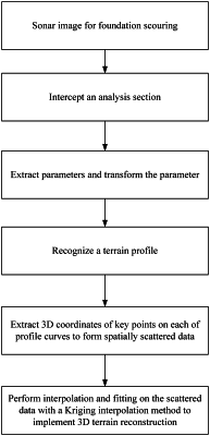
1. A three-dimensional (3D) terrain reconstruction method for a scoured area around bridge pier foundation based on a mechanical scanned imaging sonar, comprising the following steps:
step S1: scanning an overall terrain of a scoured area around bridge pier foundation with a mechanical scanning sonar device from different azimuths to acquire n sonar images of a scoured terrain in the different azimuths;
step S2: intercepting multiple analysis sections from each of acquired sonar images at a same distance;
step S3: extracting key parameters of upper and lower edges on a terrain imaging strip in each of the analysis sections in the image, and transforming extracted parameters to a 3D space according to an acoustic imaging principle, a fan-shaped beam surface of the sonar being represented with a fan-shaped arc;
step S4: recognizing, according to a relative positional relationship of fan-shaped arcs for a group of measuring points in a same analysis section, a scour terrain profile in the analysis section;
step S5: recognizing terrain profiles in different azimuths and different analysis sections one by one, and respectively extracting 3D coordinates of key points on each of profile curves to obtain required spatially scattered 3D coordinate data; and
step S6: performing interpolation and fitting on the spatially scattered data with a Kriging interpolation method, thus implementing 3D reconstruction for the foundation scouring terrain;
wherein the extracting key parameters of upper and lower edges on a terrain imaging strip in each of the analysis sections in the sonar image, and transforming extracted parameters to a 3D space according to an acoustic imaging principle in step S3 specifically comprises:
step 3a: labeling, in an analysis section pij,m at a distance dij; away from a sonar center, upper and lower edge points M, N on an imaging strip, ranges rijk, Rijk from an original sonar center point Pijk to the upper and lower edge points M, N, and a large opening angle Θ of the fan-shaped beam surface;
step 3b: drawing a circular arc with the upper edge point M as a center and the rijk as a radius, an intersection with the analysis section pij,m being an equivalent sonar center point Qijk and the equivalent sonar center point Qijk being Tijk higher than a plane where the original sonar center is located; drawing a fan-shaped arc with the equivalent sonar center point Qijk that is Tijk higher than the plane where the sonar is located as a center, the rijk as a radius, and the large opening angle Θ of the fan-shaped beam surface to obtain a corresponding fan-shaped arc Aijk Bijk of the upper edge point M in the 3D space; drawing a circular arc with the lower edge point N as a center and Rijk as a radius, an intersection with the analysis section pij,m being an equivalent sonar center point Kijk that is tijk higher than the plane where the original sonar center is located; and drawing a fan-shaped arc with the Kijk as a center, the Rijk as a radius and the angle Θ to obtain a corresponding fan-shaped arc Cijk Dijk of the lower edge point N in the 3D space, where the superscript i represents a pier No., the first subscript j represents an azimuth in which a group of measuring points are located relative to a bridge pier, the second subscript k represents a specific measuring point in the group of measuring points, and k is 0, 1 and 2 representing left, middle and right measuring points in the group of measuring points; and
step 3c: applying the same parameter transformation method to another two measuring points in the group of measuring points, to obtain a relative positional relationship in the 3D space for fan-shaped arcs corresponding to images for the group of measuring points in the same analysis section.
|