| CPC G01R 15/202 (2013.01) [G01R 19/10 (2013.01); H01R 4/30 (2013.01); H02K 5/225 (2013.01); H02K 11/27 (2016.01); H02K 2211/03 (2013.01)] | 27 Claims |

|
1. A power connector configured to conduct a current of a power device and deliver the current to a load, the power connector comprising:
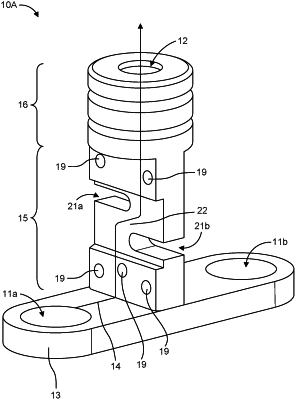
a conductive frame comprising a base structure, an extension structure, and a connector head structure that define a current path for the current,
wherein the base structure is coupled to an output node of at least one primary conductor of the power device, wherein the base structure is configured to receive the current from the at least one primary conductor, and wherein the base structure laterally extends from the extension structure in opposite lateral directions to form a first T-shape with the extension structure,
wherein the connector head structure is arranged relative to the base structure, wherein the connector head structure is configured to mechanically couple the power connector to an electrical interface of the load, wherein the connector head structure is configured to receive the current from the base structure and output the current from the power connector to the electrical interface of the load, wherein a first portion of the connector head structure laterally extends from the extension structure in a first lateral direction corresponding to one of the opposite lateral directions, and wherein the first portion of the connector head structure laterally extends over a first portion of the base structure to define a first recess that is at least partially defined by a first space that extends vertically between the first portion of the connector head structure and the first portion of the base structure,
wherein the extension structure is coupled to and vertically extends between the base structure and the connector head structure, wherein the extension structure is configured to receive the current from the base structure and deliver the current to the connector head structure,
wherein the extension structure includes a current constriction region coupled between two current non-constriction regions, wherein the current constriction region is configured to increase a magnetic flux density of a magnetic field produced by the current flowing through the current constriction region relative to a magnetic flux density of a magnetic field produced by the current flowing through the two current non-constriction regions; and
a magnetic current sensor arranged in the first recess at a position relative to the current constriction region to receive the magnetic field having the increased magnetic flux density produced by the current flowing through the current constriction region, wherein the magnetic current sensor is configured to generate a sensor signal based on the magnetic field.
|