| CPC F04B 27/18 (2013.01) [F04B 27/0873 (2013.01); F04B 27/1804 (2013.01); F04B 2027/185 (2013.01); F04B 2027/1813 (2013.01); F04B 2027/1827 (2013.01); F04B 2027/1831 (2013.01)] | 20 Claims |

|
1. A variable displacement compressor which is configured to vary a discharge volume by supplying a refrigerant in a discharge chamber to a controlled pressure chamber through a supply passage and also discharging a refrigerant in the controlled pressure chamber to a suction chamber through a discharge passage so as to adjust a pressure in the controlled pressure chamber, the variable displacement compressor comprising:
a first control valve configured to adjust an opening degree of the supply passage;
a check valve that is provided in the supply passage at a position closer to the controlled pressure chamber than the first control valve and is configured to block a refrigerant flowing from the controlled pressure chamber toward the first control valve;
a throttle passage configured to discharge a refrigerant in a region of the supply passage between the first control valve and the check valve to the suction chamber; and
a second control valve configured to adjust an opening degree of the discharge passage,
wherein the second control valve includes:
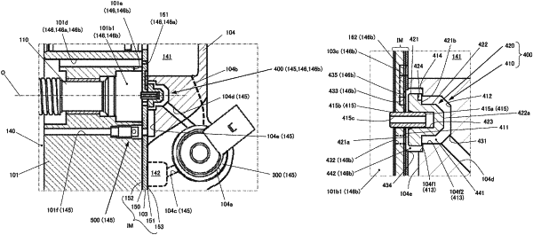
a valve chamber having a first end wall surface, a second end wall surface that faces the first end wall surface, a peripheral wall surface that extends between the first end wall surface and the second end wall surface, and an extended surface that extends radially inward from an intermediate portion in an extending direction of the peripheral wall surface, in which a first port that communicates with the region is open to the second end wall surface or to a portion of the peripheral wall surface closer to the second end wall surface than the extended surface, and a second port that communicates with the controlled pressure chamber and also constitutes a part of the discharge passage and a third port that communicates with the suction chamber and also constitutes a part of the discharge passage are open to the first end wall surface; and
a valve body having a first end surface and a second end surface that opposes the first end surface and being accommodated in the valve chamber so as to move inside the valve chamber based on a differential pressure between the region and the controlled pressure chamber,
wherein when the first control valve opens the supply passage and then a pressure in the region becomes higher than a pressure in the controlled pressure chamber, the first end surface of the valve body comes into contact with the first end wall surface of the valve chamber, to close the second port and the third port, with which the discharge passage is adjusted to a minimum opening degree, whereas when the first control valve closes the supply passage and then the pressure in the region becomes lower than the pressure in the controlled pressure chamber, the first end surface of the valve body separates from the first end wall surface of the valve chamber, to open the second port and the third port, with which the discharge passage is adjusted to a maximum opening degree and also the second end surface of the valve body comes into contact with the extended surface of the valve chamber, to partition the inside of the valve chamber into a first space to which the first port is open and a second space to which the second port and the third port are open, or the second end surface of the valve body comes into contact with the second end wall surface of the valve chamber, to minimize a gap between the extended surface and an opposite surface of the valve body that faces the extended surface, and
wherein the valve chamber includes a valve body support portion that supports a radially center portion of the valve body so that the valve body is movable in a direction perpendicular to the first end wall surface without contact with the peripheral wall surface.
|