| CPC F02M 55/008 (2013.01) | 8 Claims |

|
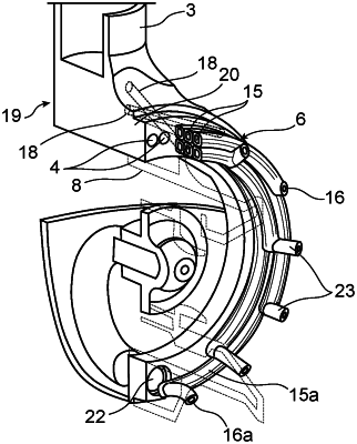
1. A fuel injection device for a combustion chamber of an aircraft engine, including a first, central, pilot injection part defining a central axis of the fuel injection device, a second, multipoint injection part surrounding the first, central, pilot injection part, the second, multipoint injection part being connected to a fuel supply conduit and including injection holes for injecting a fuel into the combustion chamber, wherein the second, multipoint injection part includes, between said injection holes and said supply conduit, at least one group of conduits comprising a plurality of conduits, said conduits of the plurality of conduits being juxtaposed to each other, and conveying separate fuel flows from a common fuel supply chamber to a single respective injection hole of the injection holes, the plurality of conduits extending circumferentially around the first, central, pilot injection part over angular sectors having different angular extensions; the plurality of conduits are composed of joined and rigid tubes forming a unitary portion and is manufactured by a material addition method; the fuel injection device also including an outer crown for supplying the first, central, pilot injection part with the fuel, said conduits of the plurality of conduits of the second, multipoint injection part being comprised in said outer crown, the second, multipoint injection part being arranged in a cavity of said outer crown which envelopes the second, multipoint injection part and which is a seat of a permanent flow of the fuel during flight so that the second, multipoint injection part is bathed by the fuel intended for the first, central, pilot injection part to maintain the fuel of the multipoint injection part below coking,
wherein each tube of the joined, rigid tubes extends from the common fuel supply chamber and terminates at the respective injection hole,
wherein at least two tubes of the joined, rigid tubes extend in a same circumferential direction.
|