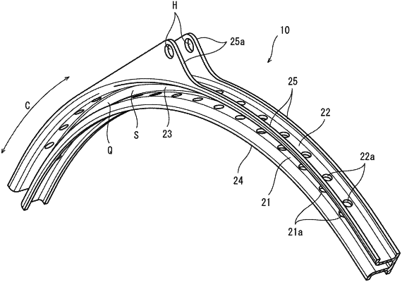
| CPC F02C 7/042 (2013.01) [F05D 2250/90 (2013.01); F05D 2300/44 (2013.01); F05D 2300/6034 (2013.01)] | 6 Claims |

|
1. A unison ring of a gas turbine engine including a compressor, a combustor, and a turbine,
the unison ring being located along an outer periphery of a casing of the gas turbine engine and coupled to variable stator vanes of the compressor,
the unison ring comprising:
an annular body including fiber-reinforced resin or circular-arc bodies including the fiber-reinforced resin, the fiber-reinforced resin including resin and reinforced fibers; and
pin holes in which a pin is in a radial direction orthogonal to an axial direction of the unison ring, wherein
a main orientation of the reinforced fibers of the fiber-reinforced resin is directed in a circumferential direction of the unison ring,
the unison ring further comprises:
an inner plate including a first pin hole of the pin holes and main surfaces facing the radial direction;
an outer plate including a second pin hole of the pin holes and main surfaces facing the radial direction, the inner plate and the outer plate being located concentrically;
a coupling plate including main surfaces facing the axial direction, the coupling plate coupling the inner plate to the outer plate; and
at least one flange plate portion including main surfaces facing the axial direction, the at least one flange plate projecting in the radial direction from at least one of an end of the inner plate in the axial direction or an end of the outer plate in the axial direction, and
the at least one flange plate portion comprises a pair of inner flange plates projecting inward in the radial direction from both ends of the inner plate in the axial direction.
|