| CPC F01D 25/246 (2013.01) [F01D 11/08 (2013.01); F05D 2240/11 (2013.01); F05D 2300/6033 (2013.01)] | 17 Claims |

|
1. A turbine shroud assembly for use with a gas turbine engine, the turbine shroud assembly comprising
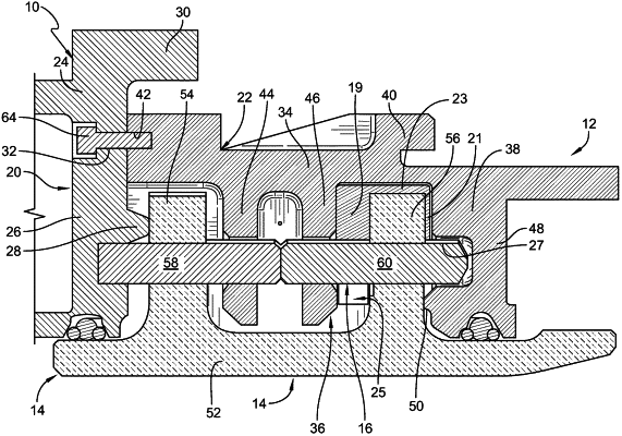
a carrier assembly made of metallic materials and arranged circumferentially at least partway around an axis, the carrier assembly including an outer wall, a forward mount wall that extends radially inward from the outer wall, an intermediate mount that includes a first intermediate mount wall that extends radially inward from the outer wall and a second intermediate mount wall that extends radially inward from the outer wall, and an aft mount wall axially spaced apart from the intermediate mount and that extends radially inward from the outer wall, wherein the aft mount wall includes an aft flange and a chordal seal that extends axially away from the aft flange,
a blade track segment made of ceramic matrix composite materials, the blade track segment supported by the carrier assembly to locate the blade track segment radially outward of the axis and define a portion of a gas path of the turbine shroud assembly, and the blade track segment including a shroud wall that extends circumferentially partway around the axis, a first attachment flange that extends radially outward from the shroud wall into a forward space between the forward mount wall and the first intermediate mount wall, and a second attachment flange that extends radially outward from the shroud wall into an aft space between the second intermediate mount wall and the aft mount wall,
a retainer that includes a forward pin that extends through the first attachment flange and into the first intermediate mount wall and an aft pin that extends into the second intermediate mount wall, through the second attachment flange, and into the aft mount wall so as to couple the blade track segment to the carrier assembly, and
a clip shim arranged around the second attachment flange and configured to engage the second attachment flange and the second intermediate mount wall and urge the second attachment flange axially aft relative to the axis and into engagement with the chordal seal.
|
|
17. A method of forming a turbine shroud assembly, comprising
providing a carrier assembly having an outer wall, a first mount wall that extends radially inward from the outer wall, an intermediate mount that extends radially inward from the outer wall, and a second mount wall axially spaced apart from the intermediate mount and that extends radially inward from the outer wall,
providing a blade track segment made of ceramic matrix composite materials, the blade track segment including a shroud wall that extends circumferentially partway around the axis, a first attachment flange that extends radially outward from the shroud wall, and a second attachment flange that extends radially outward from the shroud wall,
arranging a clip shim between the intermediate mount and the second attachment flange to cause the clip shim to urge the second attachment flange toward the second mount wall, and
inserting a retainer into the first mount wall, the first attachment flange, the intermediate mount, the second attachment flange, and the second mount wall,
wherein the second mount wall is formed to include a flange and a chordal seal that extends axially away from the flange and engages the second attachment flange,
wherein the clip shim includes a top wall that extends axially, a shim wall that extends radially from the top wall and is located axially between and engaged with the intermediate mount and the second attachment flange, and a clip wall that is spaced apart from the shim wall and extends radially from the top wall along the second attachment flange.
|