| CPC E21B 47/11 (2020.05) [E21B 49/10 (2013.01); E21B 43/12 (2013.01); E21B 43/162 (2013.01); E21B 47/10 (2013.01)] | 20 Claims |

|
12. A method of operating a hydrocarbon well, comprising:
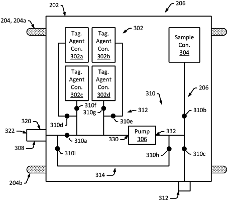
disposing a downhole fluid acquisition and injection tool downhole in a wellbore of a hydrocarbon well extending into a formation containing a hydrocarbon reservoir, the downhole fluid acquisition and injection tool comprising:
tagging agent containers configured to house tagging agents, the containers comprising:
a first tagging agent container configured to house a first tagging agent; and
a second tagging agent container configured to house a second tagging agent;
a fluid sample container configured to house reservoir fluid extracted from the hydrocarbon reservoir;
a fluid port configured to contact a surface of the formation to facilitate the communication of fluids between the hydrocarbon reservoir and the downhole fluid acquisition and injection tool;
a fluid pump configured to:
pump, into the fluid sample container, reservoir fluid extracted from the hydrocarbon reservoir by way of the fluid port; and
pump, into the hydrocarbon reservoir by way of the fluid port, tagging agents from the tagging agent containers;
fluid control valves configured to:
route reservoir fluid extracted from the hydrocarbon reservoir by way of the fluid port to the pump and into the fluid sample container; and
route tagging agents from the tagging agents containers to the pump and into the hydrocarbon reservoir by way of the fluid port;
an isolation system configured to isolate a test interval of the formation from interference of adjacent formations or the wellbore,
the test interval comprising an annular region of the wellbore between the wall of the wellbore and a body of the downhole fluid acquisition and injection tool,
the isolation system comprising:
an upper packer configured to seal against the wall of the wellbore to isolate the test interval from an upper portion of the wellbore located up-hole of the downhole fluid acquisition and injection tool; and
a lower packer configured to seal against the wall of the wellbore to isolate the test interval from a lower portion of the wellbore located downhole of the downhole fluid acquisition and injection tool;
an output/cleaning port configured to be in fluid communication with the lower or upper portion of the wellbore;
the fluid control valves comprising:
a sample valve configured to regulate flow of reservoir fluid between the fluid port and an inlet of the pump;
a sample-container valve configured to regulate flow of reservoir fluid between the pump and the sample container;
an output/cleaning valve configured to regulate flow of reservoir fluid between an output of the pump and the output/cleaning port; and
a tagging valve system configured to regulate flow of tagging agents between tagging agent containers and the input of the pump, the tagging valve system comprising:
a first tagging valve configured to regulate flow of the first tagging agent between the first tagging agent container and the inlet of the pump; and
a second tagging valve configured to regulate flow of the second tagging agent between the second tagging agent container and the inlet of the pump; and
injection valve system configured to regulate flow of the tagging agents between the output of the pump and the fluid port, the injection valve system comprising a first injection valve between the output of the pump and the fluid port; and
operating the downhole fluid acquisition and injection tool to conduct a sampling operation to collect a fluid sample from the reservoir and one or more tagging operations at different depths along the wellbore to inject the first and second tagging agents into the reservoir.
|