| CPC B65D 47/2031 (2013.01) [B65D 35/46 (2013.01)] | 14 Claims |

|
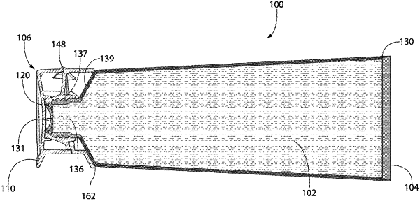
1. A container comprising:
a chamber containing a viscous fluidic material;
a dispensing passageway for discharging the viscous fluidic material from the chamber;
a resilient valve operably coupled to the dispensing passageway, the resilient valve comprising:
a valve head; and
an orifice in the valve head, the orifice defined by an orifice edge of the valve head; and
a nozzle comprising at least a portion of the dispensing passageway, the nozzle terminating in an annular distal-most surface that defines a dispensing opening of the dispensing passageway;
the resilient valve configured to: (1) transition from a normal state to a dispensing state upon a discharge pressure being applied to the chamber to allow the viscous fluidic material to be passed through the orifice of the resilient valve and be dispensed from the dispensing passageway as a string of the viscous fluidic material, the orifice being open in the normal state; and (2) return from the dispensing state to the normal state upon cessation of the discharge pressure, the resilient valve assuming a pinching state while returning from the dispensing state to the normal state in which the string of the viscous fluidic material is pinched off by the orifice edge;
the resilient valve comprising an annular ring defining a central opening, the valve head supported by the annular ring within the central opening, the annular ring comprising an upper-most surface; and
the resilient valve mounted within the nozzle so that the upper-most surface of the annular ring of the resilient valve is substantially flush with and surrounded by the annular distal-most surface of the nozzle.
|