| CPC B24B 57/02 (2013.01) [B24B 37/005 (2013.01); B24B 37/10 (2013.01); B24B 37/34 (2013.01)] | 10 Claims |

|
1. A polishing apparatus, comprising:
a polishing table configured to support a polishing pad;
a top ring configured to press a substrate against the polishing pad; and
a liquid supply mechanism configured to supply a liquid onto the polishing pad,
wherein the liquid supply mechanism comprises:
a nozzle arm configured to be movable in a radial direction of the polishing table;
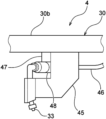
a slurry nozzle attached to the nozzle arm;
a liquid ejection nozzle attached to the nozzle arm, the liquid ejection nozzle configured to form a fan-shaped liquid spray pattern, the liquid ejection nozzle having a liquid passage surface, a liquid ejection surface, and a liquid throttle surface, the liquid throttle surface being formed on an inner surface of the liquid ejection nozzle and having a tapered shape;
a slurry line coupled to the liquid ejection nozzle and configured to supply a polishing liquid;
a coupling member connected to the slurry line; and
a flushing line coupled to the liquid ejection nozzle by way of a connection to the coupling member, the flushing line configured to supply a flushing liquid for cleaning the liquid ejection nozzle, wherein the flushing liquid flows through the flushing line to the slurry line by way of the coupling member.
|