| CPC B01L 3/502715 (2013.01) [B01L 3/50273 (2013.01); H03K 17/725 (2013.01); B01L 2300/0645 (2013.01)] | 17 Claims |

|
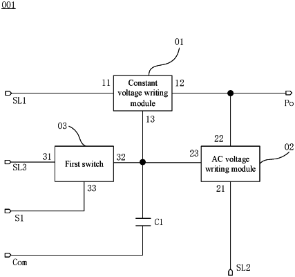
1. A driving circuit, comprising:
a constant voltage writing module, wherein the constant voltage writing module comprises an input terminal electrically connected to a first signal line, an output terminal electrically connected to an output terminal of the driving circuit, and a control terminal; and the constant voltage writing module is configured to transmit a constant voltage to the output terminal of the driving circuit;
an alternating current (AC) voltage writing module, wherein the AC voltage writing module comprises an input terminal electrically connected to a second signal line, an output terminal electrically connected to the output terminal of the driving circuit, and a control terminal; and the AC voltage writing module is configured to transmit an alternating current (AC) voltage to the output terminal of the driving circuit;
a first switch, wherein the first switch comprises an input terminal electrically connected to a third signal line, an output terminal electrically connected to the control terminal of the AC voltage writing module and the control terminal of the constant voltage writing module, and a control terminal electrically connected to a first scan line; and
a first capacitor, wherein the first capacitor comprises one electrode plate electrically connected to the output terminal of the first switch, and another electrode plate electrically connected to a reference signal line.
|