| CPC A61M 5/385 (2013.01) [A61M 5/158 (2013.01); A61M 5/165 (2013.01); A61M 39/0693 (2013.01); A61M 39/26 (2013.01); A61M 2205/7536 (2013.01)] | 13 Claims |

|
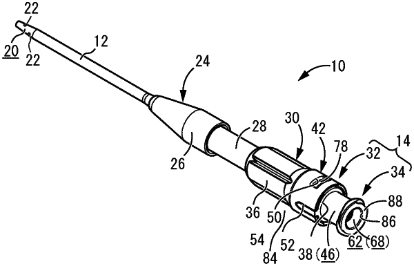
1. A hemostasis valve-equipped indwelling needle comprising:
a cannula provided on a distal end side thereof and configured to be percutaneously inserted into a blood vessel;
a link connector provided on a proximal end side thereof;
an internal flow path extending from the cannula to the link connector; and
a hemostasis valve disposed inside the link connector, wherein
the link connector includes an air vent passage that communicates with an external space via an air outlet port opening onto a circumferential wall thereof,
the internal flow path communicates with the external space further on a cannula side than the hemostasis valve via the air vent passage, and
a filter that allows gas to pass through but does not allow liquid to pass through is clasped directly by and compressed between opposing surfaces of a plurality of rigid members and disposed on the air vent passage.
|