| CPC A61B 17/072 (2013.01) [A61B 17/068 (2013.01); A61B 17/0682 (2013.01); A61B 17/07207 (2013.01); A61B 17/105 (2013.01); A61B 17/1155 (2013.01); A61B 17/32053 (2013.01); A61B 2017/07235 (2013.01); A61B 2017/07242 (2013.01); A61B 2017/07264 (2013.01); A61B 2017/07278 (2013.01); A61B 2017/320052 (2013.01)] | 20 Claims |

|
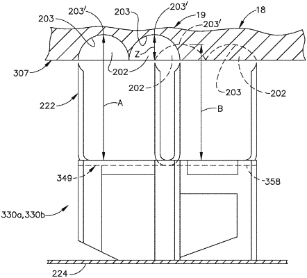
1. An end effector for a surgical fastening instrument, said end effector comprising:
a frame defining a longitudinal axis;
a first jaw, comprising:
a cartridge body;
a plurality of fastener cavities defined in said cartridge body;
an arcuate row of first fasteners removably stored in said cartridge body, wherein each said first fastener comprises:
a first base; and
a first pair of legs extending from said first base, wherein a first unfired height is defined by said first base and said first pair of legs; and
an arcuate row of second fasteners removably stored in said cartridge body, wherein said arcuate row of second fasteners extends alongside said arcuate row of first fasteners, and wherein each said second fastener comprises:
a second base; and
a second pair of legs extending from said second base, wherein a second unfired height is defined by said second base and said second pair of legs;
a second jaw comprising an arcuate anvil configured to deform said first fasteners to a first fired height and said second fasteners to a second fired height, wherein said first fired height is different than said second fired height, wherein said arcuate anvil comprises a tissue-compression surface extending transverse to said longitudinal axis, and wherein said tissue-compression surface defines a plurality of fastener-forming pockets;
first fastener-supporting surfaces configured to advance said first fasteners toward said arcuate anvil during a fastener firing stroke; and
second fastener-supporting surfaces configured to advance said second fasteners toward said arcuate anvil during said fastener firing stroke.
|