US 12,160,035 B2
Methods of manufacturing an antenna for an implantable electronic device and related implantable electronic devices
Armando M. Cappa, Granada Hills, CA (US); Jorge N. Amely-Velez, Simi Valley, CA (US); Alan B. Vogel, Santa Clarita, CA (US); Wisit Lim, Santa Clarita, CA (US); John R. Gonzalez, McKinney, TX (US); Alexander Robertson, Los Angeles, CA (US); Alex Soriano, Ventura, CA (US); Evan Sheldon, Sherman Oaks, CA (US); Perry Li, Arcadia, CA (US); and Jeffery Crook, Belmont, CA (US)
Assigned to Pacesetter, Inc., Sylmar, CA (US)
Filed by Pacesetter, Inc., Sylmar, CA (US)
Filed on Apr. 25, 2023, as Appl. No. 18/138,872.
Application 18/138,872 is a continuation of application No. 17/512,420, filed on Oct. 27, 2021, granted, now 11,670,843.
Application 17/512,420 is a continuation of application No. 16/773,195, filed on Jan. 27, 2020, granted, now 11,189,915, issued on Nov. 30, 2021.
Application 16/773,195 is a continuation of application No. 15/633,614, filed on Jun. 26, 2017, granted, now 10,587,038, issued on Mar. 10, 2020.
Claims priority of provisional application 62/419,868, filed on Nov. 9, 2016.
Prior Publication US 2023/0261368 A1, Aug. 17, 2023
This patent is subject to a terminal disclaimer.
Int. Cl. H01Q 1/27 (2006.01); A61N 1/372 (2006.01); H01Q 1/22 (2006.01); H01Q 1/38 (2006.01); H01Q 5/364 (2015.01); H01Q 9/40 (2006.01); H01Q 9/42 (2006.01)
CPC H01Q 1/38 (2013.01) [A61N 1/37229 (2013.01); H01Q 1/22 (2013.01); H01Q 1/273 (2013.01); H01Q 5/364 (2015.01); H01Q 9/40 (2013.01); H01Q 9/42 (2013.01)] 8 Claims
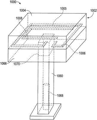
OG exemplary drawing
 
1. A method of manufacturing an implantable electronic device, the method comprising:
forming an antenna of the implantable electronic device, the antenna comprising an antenna trace within a dielectric antenna body, the antenna trace including:
a first trace portion disposed in a first transverse layer and defining a first trace path;
a second trace portion disposed in a second transverse layer longitudinally offset from the first transverse layer and defining a second trace path,
wherein, if projected to be coplanar, the first trace path defines a trace boundary and the second trace path is within the trace boundary; and
forming a capacitive feature extending to partially overlap the first or second trace portions.