| CPC G03G 15/0887 (2013.01) [B07B 7/083 (2013.01); G03G 9/0817 (2013.01)] | 9 Claims |

|
1. A toner classification apparatus comprising:
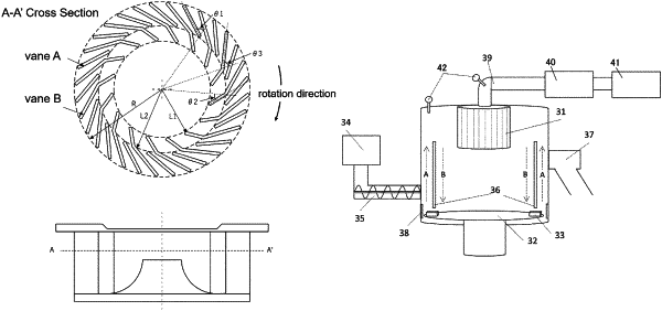
a classification rotor; wherein
the classification rotor comprises a plurality of vanes which extend from a rotation center direction of the classification rotor to an outer circumference direction of the classification rotor,
the plurality of vanes are disposed with prescribed gaps established between the vanes;
the gaps form an opening which faces a rotation center area of the classification rotor;
the plurality of vanes comprise a first vane group constituted by a vane A and a second vane group constituted by a vane B having a length longer than a length of the vane A,
the lengths of the vanes A are substantially identical to each other and the vanes A are disposed at an interval so as to follow paths which are substantially identical to each other during rotation of the classification rotor,
the lengths of the vanes B are substantially identical to each other and the vanes B are disposed at an interval so as to follow paths which are substantially identical to each other during the rotation of the classification rotor,
a number of the vanes A which are disposed between two adjacent vanes B is one to three,
the vane B has a first elbow,
the vane A and the vane B are disposed such that a portion of a vane away from of the rotation center of the classification rotor is located on more upstream direction in a direction of rotation of the classification rotor than a portion of the vane closer to the rotation center of the classification rotor,
a distance between the rotation center of the classification rotor and the end portion on the side of the outer circumference of the vane A and a distance between the rotation center of the classification rotor and the end portion on the side of the outer circumference of the vane B are substantially equal to each other,
a distance between the rotation center of the classification rotor and the end portion on the side of the rotation center of the vane A and a distance between the rotation center of the classification rotor and the first elbow of the vane B are substantially equal to each other,
the distance between the rotation center of the classification rotor and the end portion on the side of the rotation center of the vane A is more than a distance between the rotation center of the classification rotor and the end portion on the side of the rotation center of the vane B, and, in a cross section obtained when the classification rotor is cut in a direction perpendicular to a rotation axis of the classification rotor,
(i) an angle θ1 (° ) formed by a straight line which connects the rotation center of the classification rotor and the end portion on the side of the rotation center of the vane A and a portion on the vane A which is closer to the side of the outer circumference than the end portion on the side of the rotation center of the vane A is 40 to 65°,
(ii) an angle θ3 (° ) formed by a straight line which connects the rotation center of the classification rotor and the first elbow of the vane B and a portion on the vane B which is closer to the side of the outer circumference than the first elbow of the vane B is substantially identical to the angle θ1,
(iii) an angle θ2 (° ) formed by the straight line which connects the rotation center of the classification rotor and the first elbow of the vane B and a straight line which connects the end portion on the side of the rotation center of the vane B and the first elbow of the vane B satisfies
0°≤θ2≤θ3×½,
(iv) when a radius of the classification rotor is represented by R and the distance between the rotation center of the classification rotor and the end portion on the side of the rotation center of the vane B is represented by L1, the R and the L1 satisfy
0.35≤L1/R≤0.65, and
(v) when the distance between the rotation center of the classification rotor and the first elbow of the vane B is represented by L2, the R, the L1, and the L2 satisfy
0.35≤(L2−L1)/(R−L1)≤0.70.
|