| CPC F16F 9/49 (2013.01) [F16F 9/185 (2013.01); F16F 9/3405 (2013.01); F16F 2230/42 (2013.01); F16F 2234/02 (2013.01); F16F 2234/04 (2013.01)] | 12 Claims |

|
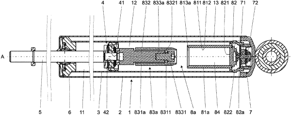
1. A hydraulic damper (1), comprising:
a main tube (3) filled with working liquid;
a main piston assembly (4) disposed slidably inside the main tube (3) along an axis (A), attached to a piston rod (5) led outside the hydraulic damper (1) through a sealed piston rod guide (6), dividing the main tube (3) into a rebound chamber (11) and a compression chamber (12), to control the flow of working liquid passing between the rebound chamber (11) and the compression chamber (12);
a base valve assembly (7) located at the end of the compression chamber (12) to control the flow of working liquid passing between the compression chamber (12) and an additional compensation chamber (13); and
a hydraulic compression stop assembly (8) located in the compression chamber (12) and comprising:
an insert (81) fixed on the base valve assembly (7), configured to allow the flow of fluid between the insert (81) and the main tube (3) through the base valve assembly (7), and provided with a first inner chamber (84), and
an additional piston assembly (83) displaceable along with the main piston assembly (4) and apt to be introduced inside the first inner chamber (84) of the insert (81) at the end of the hydraulic damper compression stroke to generate additional damping force,
wherein said additional piston assembly (83) comprises: a piston rod extender (832) fixed to the main piston assembly (4) or the piston rod (5) at the side of the compression chamber (12), and a tenon (831) fixed to said piston rod extender (832) and radially displaceable with regard to said piston rod extender (832), and
wherein said tenon (831) is terminated with a first entry surface (8316) having diameter monotonically diminishing towards the compression end of said tenon (831), while the insert (81) is provided with a second entry surface (813) having diameter monotonically increasing towards the rebound end of the insert (81).
|